2 - 36
SPEC
CABLE ROUTING
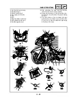
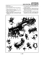
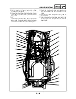
Î
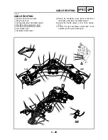
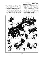
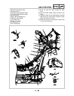
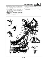
Connect the orange lead to the upper terminal of
the ignition coil and connect the red/black lead to
the lower terminal.
Ï
Fasten the throttle cables, sidestand switch lead,
and wire harness with a plastic holder as shown.
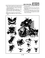
³
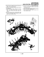
Fasten the sub-wire harness, stator coil lead
coupler, and wire harness with a plastic locking
tie. Face the end of the plastic locking tie down.
Ñ
Install the plastic locking tie in the hole above
the footrest bracket.
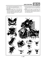
Ò
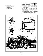
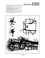
Fasten the sub-wire harness at the white tape
and the crankshaft position sensor/stator coil
lead to the engine bracket with a plastic locking
tie. Face the end of the plastic locking tie away
from the scooter.
Ó
Route the rear brake hose and rear brake lock
lever cable through the two engine bracket
guides so that the rear brake lock lever cable is
towards the outside of the scooter.
H
I
D
D
4
3
5
Ó
8
7
È
1
I
H
Ï
F
G
G
Ñ
C-C
A-A
3
4
5
B-B
3
J
G
Ð
C
C
A
A
B
B
B
6
É
9
E
E
J
J
8
7
L
M
B
Ö
Ø
Ù
Û
Ú
Ü
7
8
G
Ô
F
K
6
Õ
8
O
G
N
7
Þ
I
5
4
3
Ý
J-J
M
F
G
G
H
E-E
×
7
8
Ê
7
0
A
Ë
Ì
Í
B
2
1
C
D
E
Î
G
Ò
Summary of Contents for 2004 YP400
Page 1: ...2004 YP400 S 5RU1 AE1 SERVICE MANUAL ...
Page 2: ......
Page 8: ......
Page 9: ...GEN INFO 1 ...
Page 11: ...GEN INFO ...
Page 28: ...SPEC 2 ...
Page 30: ...SPEC ...
Page 77: ...CHK ADJ 3 ...
Page 137: ......
Page 138: ...CHAS 4 ...
Page 210: ......
Page 211: ...ENG 5 ...
Page 286: ...COOL 6 ...
Page 288: ...COOL ...
Page 299: ...FI 7 ...
Page 301: ...FI ...
Page 342: ...ELEC 8 ...
Page 378: ...8 34 ELEC LIGHTING SYSTEM ...
Page 404: ......
Page 405: ...TRBL SHTG 9 ...
Page 415: ......
Page 416: ...YAMAHA MOTOR CO LTD 2500 SHINGAI IWATA SHIZUOKA JAPAN ...

