FUEL TANK
6-2
EAS26630
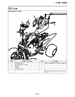
REMOVING THE FUEL TANK
1. Remove:
• Fuel hose (fuel cock side)
ECA14700
Although the fuel has been removed from the
fuel tank be careful when removing the fuel
hoses, since there may be fuel remaining in it.
TIP
Before removing the hose, turn the fuel cock to
“OFF” and place a few rags in the area under
where it will be removed.
2. Remove:
• Fuel tank
TIP
When installing the fuel tank, pass the fuel
tank breather hose through the hole in the han-
dlebar protector.
EAS26650
CHECKING THE FUEL COCK
1. Check:
• Fuel cock
Cracks/damage/wear
→
Replace.
2. Check:
• Fuel cock strainer
Obstruction
→
clean.
Blow out the jets with compressed air.
Damage
→
Replace.
EAS26660
CHECKING THE FUEL COCK OPERATION
TIP
After installing the fuel cock, check its opera-
tion.
1. Check:
• Fuel cock operation
Out of specification
→
Replace the fuel
cock.
▼▼▼▼▼▼▼▼▼▼▼▼▼▼▼▼▼▼▼▼▼▼▼▼▼▼▼▼▼▼
a. Check that the fuel cock lever is turned to
“ON” or “RES”.
b. Place a container under the end of the fuel
hose.
c. Suck on the end of the vacuum hose.
▲▲▲▲▲▲▲▲▲▲▲▲▲▲▲▲▲▲▲▲▲▲▲▲▲▲▲▲▲▲
Fuel flows.
Fuel cock is OK.
Fuel does not flow.
Replace the fuel cock.
Summary of Contents for 2009 YFM25RY
Page 1: ...SERVICE MANUAL YFM25RY YFM25RSEY YFM25RSE2Y 4D3 28197 11 LIT 11616 22 09 2009 ...
Page 8: ......
Page 39: ...LUBRICATION POINTS AND LUBRICANT TYPES 2 20 ...
Page 42: ...LUBRICATION SYSTEM CHART AND DIAGRAMS 2 23 EAS20410 LUBRICATION DIAGRAMS ...
Page 44: ...LUBRICATION SYSTEM CHART AND DIAGRAMS 2 25 ...
Page 46: ...LUBRICATION SYSTEM CHART AND DIAGRAMS 2 27 ...
Page 47: ...LUBRICATION SYSTEM CHART AND DIAGRAMS 2 28 1 Oil cooler 2 Oil hose 1 3 Oil hose 2 ...
Page 48: ...CABLE ROUTING 2 29 EAS20430 CABLE ROUTING ...
Page 50: ...CABLE ROUTING 2 31 ...
Page 52: ...CABLE ROUTING 2 33 ...
Page 54: ...CABLE ROUTING 2 35 ...
Page 56: ...CABLE ROUTING 2 37 ...
Page 58: ...CABLE ROUTING 2 39 ...
Page 60: ...CABLE ROUTING 2 41 ...
Page 62: ...CABLE ROUTING 2 43 ...
Page 65: ......
Page 143: ...HANDLEBAR 4 42 Throttle cable free play 2 0 4 0 mm 0 08 0 16 in ...
Page 162: ...CHAIN DRIVE 4 61 ...
Page 165: ......
Page 240: ...CARBURETOR 6 9 ...
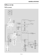
Page 242: ...IGNITION SYSTEM 7 1 EAS27090 IGNITION SYSTEM EAS27100 CIRCUIT DIAGRAM ...
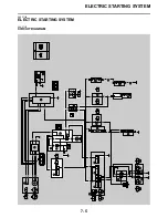
Page 246: ...ELECTRIC STARTING SYSTEM 7 5 EAS27160 ELECTRIC STARTING SYSTEM EAS27170 CIRCUIT DIAGRAM ...
Page 252: ...CHARGING SYSTEM 7 11 EAS27200 CHARGING SYSTEM EAS27210 CIRCUIT DIAGRAM ...
Page 255: ...CHARGING SYSTEM 7 14 ...
Page 256: ...LIGHTING SYSTEM 7 15 EAS27240 LIGHTING SYSTEM EAS27250 CIRCUIT DIAGRAM ...
Page 260: ...SIGNALING SYSTEM 7 19 EAS27270 SIGNALING SYSTEM EAS27280 CIRCUIT DIAGRAM ...
Page 264: ...CARBURETOR HEATING SYSTEM 7 23 EAS27490 CARBURETOR HEATING SYSTEM EAS27500 CIRCUIT DIAGRAM ...
Page 267: ...CARBURETOR HEATING SYSTEM 7 26 ...
Page 268: ...ELECTRICAL COMPONENTS 7 27 EAS27972 ELECTRICAL COMPONENTS ...
Page 270: ...ELECTRICAL COMPONENTS 7 29 EAS27980 CHECKING THE SWITCHES ...
Page 284: ...ELECTRICAL COMPONENTS 7 43 ...
Page 291: ......
Page 292: ...YAMAHA MOTOR CO LTD 2500 SHINGAI IWATA SHIZUOKA JAPAN ...
Page 293: ...WIRING DIAGRAM YFM25RY YFM25RSEY YFM25RSE2Y ...

