5-8
CARBURETOR
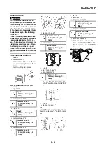
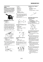
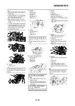
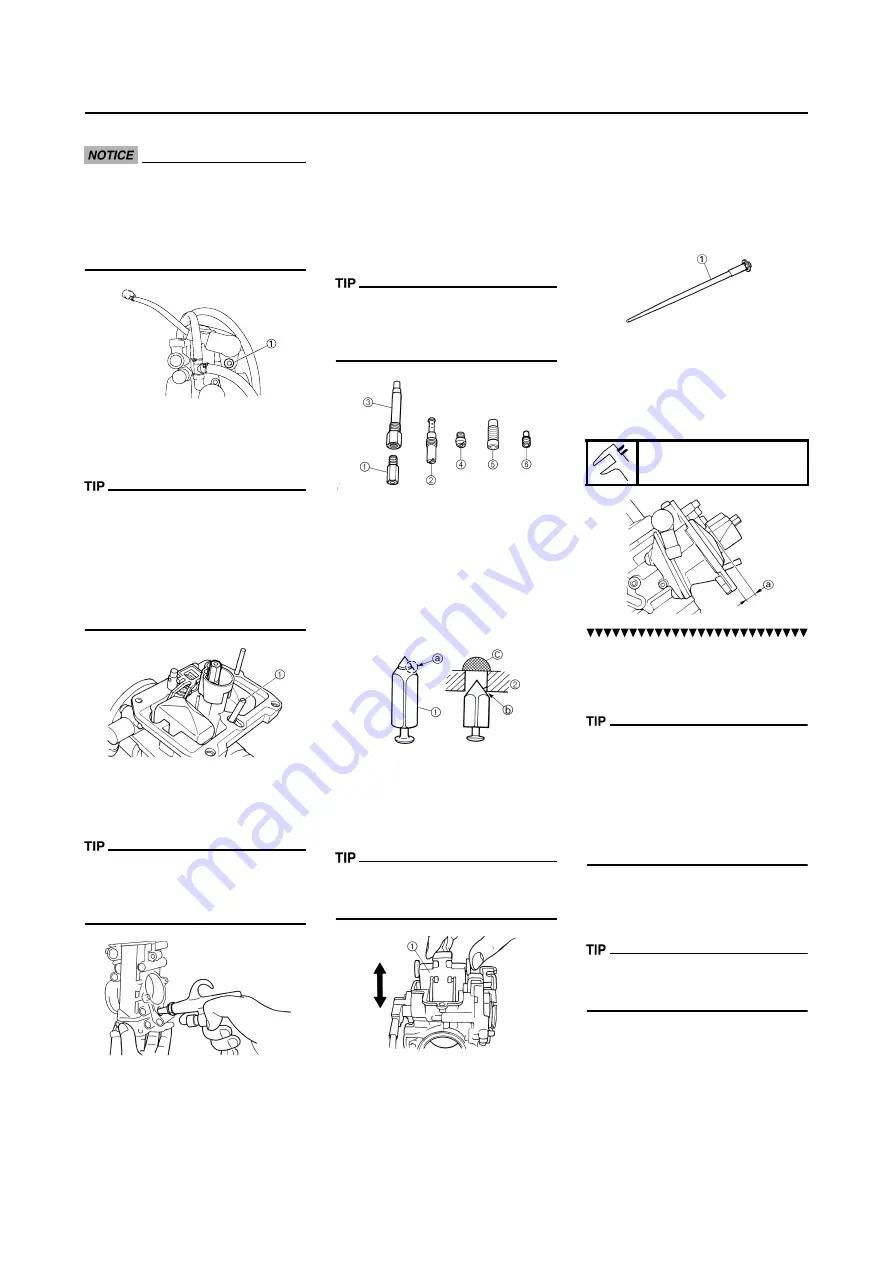
HANDLING NOTE
Do not loosen the screw (throttle
position sensor) "1" except when
changing the throttle position sen-
sor due to failure because it will
cause a drop in engine perfor-
mance.
REMOVING THE PILOT SCREW
(For EUROPE)
1. Remove:
• Pilot screw "1"
To optimize the fuel flow at a small
throttle opening, each machine's pilot
screw has been individually set at the
factory. Before removing the pilot
screw, turn it in fully and count the
number of turns. Record this number
as the factory-set number of turns
out.
CHECKING THE CARBURETOR
1. Inspect:
• Carburetor body
Contamination
→
Clean.
• Use a petroleum based solvent for
cleaning. Blow out all passages and
jets with compressed air.
• Never use a wire.
2. Inspect:
• Main jet "1"
• Pilot jet "2"
• Needle jet "3"
• Starter jet "4"
• Pilot air jet "5"
• Leak jet "6"
Damage
→
Replace.
Contamination
→
Clean.
• Use a petroleum based solvent for
cleaning. Blow out all passages and
jets with compressed air.
• Never use a wire.
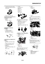
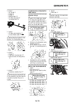
CHECKING THE NEEDLE VALVE
1. Inspect:
• Needle valve "1"
• Valve seat "2"
Grooved wear "a"
→
Replace.
Dust "b"
→
Clean.
• Filter "c"
Clogged
→
Clean.
CHECKING THE THROTTLE
VALVE
1. Check:
• Free movement
Stick
→
Repair or replace.
Insert the throttle valve "1" into the
carburetor body, and check for free
movement.
CHECKING THE JET NEEDLE
1. Inspect:
• Jet needle "1"
Bends/wear
→
Replace.
• Clip groove
Free play exists/wear
→
Replace.
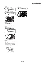
MEASURING AND ADJUSTING
THE FLOAT HEIGHT
1. Measure:
• Float height "a"
Out of specification
→
Adjust.
Measurement and adjustment
steps:
a. Hold the carburetor in an upside
down position.
• Slowly tilt the carburetor in the op-
posite direction, then take the mea-
surement when the needle valve
aligns with the float arm.
• If the carburetor is level, the weight
of the float will push in the needle
valve, resulting in an incorrect mea-
surement.
b. Measure the distance between
the mating surface of the float
chamber and top of the float using
a vernier calipers.
The float arm should be resting on the
needle valve, but not compressing
the needle valve.
c. If the float height is not within
specification, inspect the valve
seat and needle valve.
d. If either is worn, replace them
both.
Float height:
8.0 mm (0.31 in)
Summary of Contents for 2010 WR450FZ
Page 4: ......
Page 12: ...1 2 LOCATION OF IMPORTANT LABELS EUROPE ...
Page 13: ...1 3 LOCATION OF IMPORTANT LABELS AUS NZ ZA ...
Page 49: ...2 18 TIGHTENING TORQUES ...
Page 51: ...2 20 LUBRICATION DIAGRAMS 1 Intake camshaft 2 Exhaust camshaft A To main axle B From oil pump ...
Page 90: ...3 31 ELECTRICAL Charging method using a variable voltage charger ...
Page 91: ...3 32 ELECTRICAL Charging method using a constant voltage charger ...
Page 125: ...5 22 CYLINDER HEAD 3 Install Bolt cylinder head 1 Bolt cylinder head 10 Nm 1 0 m kg 7 2 ft lb ...
Page 144: ...5 41 OIL PUMP 15 Oil pump drive shaft 1 16 Rotor housing 1 Order Part name Q ty Remarks ...

