5-60
CRANKCASE AND CRANKSHAFT
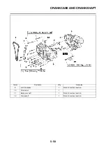
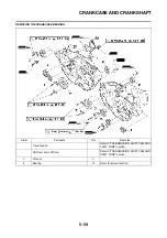
DISASSEMBLING THE
CRANKCASE
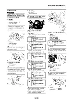
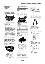
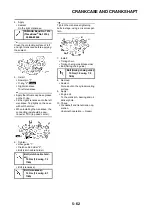
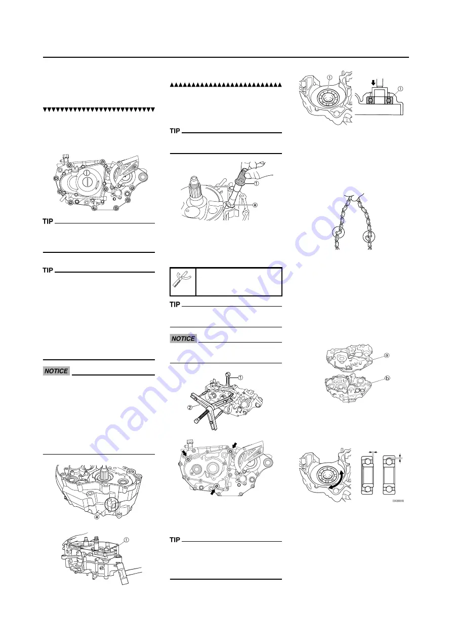
1. Separate:
• Right crankcase
• Left crankcase
Separation steps:
a. Remove the crankcase bolts,
hose guide and clutch cable hold-
er.
Loosen each bolt 1/4 of a turn at a
time and after all the bolts are loos-
ened, remove them.
b. Remove the right crankcase.
• Place the crankcase with its left
side downward and split it by insert-
ing a screwdriver tip into the split-
ting slit "a" in the crankcase.
• Lift the right crankcase horizontally
while lightly patting the case split-
ting slit and engine mounting boss
using a soft hammer, and leave the
crankshaft and transmission with
the left crankcase.
Use soft hammer to tap on the
case half. Tap only on reinforced
portions of case. Do not tap on
gasket mating surface. Work slow-
ly and carefully. Make sure the
case halves separate evenly. If the
cases do not separate, check for a
remaining case bolt or fitting. Do
not force.
c. Remove the dowel pins and O-
ring.
REMOVING THE BALANCER
SHAFT
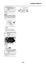
1. Remove:
• Balancer shaft "1"
Remove the balancer shaft with its
flat side "a" facing the crankshaft.
REMOVING THE CRANKSHAFT
1. Remove:
• Crankshaft "1"
Use the crankcase separating
tool "2".
Install the crankcase separating tool
as shown.
Do not use a hammer to drive out
the crankshaft.
REMOVING THE CRANKCASE
BEARING
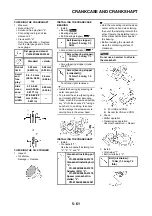
1. Remove:
• Bearing "1"
• Remove the bearing from the
crankcase by pressing its inner
race.
• Do not use the removed bearing.
CHECKING THE TIMING CHAIN
AND TIMING CHAIN GUIDE
1. Inspect:
• Timing chain
Cracks/stiff
→
Replace the timing
chain and camshaft sprocket as a
set.
2. Inspect:
• Timing chain guide
Wear/damage
→
Replace.
CHECKING THE CRANKCASE
1. Inspect:
• Contacting surface "a"
Scratches
→
Replace.
• Engine mounting boss "b", crank-
case
Cracks/damage
→
Replace.
2. Inspect:
• Bearing
Rotate inner race with a finger.
Rough spot/seizure
→
Replace.
3. Inspect:
• Oil seal
Damage
→
Replace.
Crankcase separating
tool:
YU-A9642/90890-04152
Summary of Contents for 2010 WR450FZ
Page 4: ......
Page 12: ...1 2 LOCATION OF IMPORTANT LABELS EUROPE ...
Page 13: ...1 3 LOCATION OF IMPORTANT LABELS AUS NZ ZA ...
Page 49: ...2 18 TIGHTENING TORQUES ...
Page 51: ...2 20 LUBRICATION DIAGRAMS 1 Intake camshaft 2 Exhaust camshaft A To main axle B From oil pump ...
Page 90: ...3 31 ELECTRICAL Charging method using a variable voltage charger ...
Page 91: ...3 32 ELECTRICAL Charging method using a constant voltage charger ...
Page 125: ...5 22 CYLINDER HEAD 3 Install Bolt cylinder head 1 Bolt cylinder head 10 Nm 1 0 m kg 7 2 ft lb ...
Page 144: ...5 41 OIL PUMP 15 Oil pump drive shaft 1 16 Rotor housing 1 Order Part name Q ty Remarks ...

