6-13
FRONT BRAKE AND REAR BRAKE
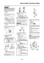
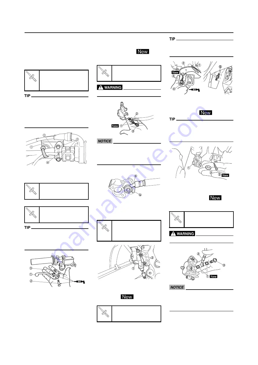
INSTALLING THE FRONT BRAKE
MASTER CYLINDER
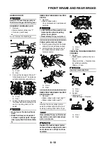
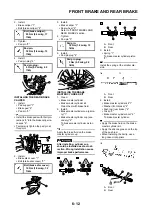
1. Install:
• Brake master cylinder "1"
• Brake master cylinder bracket "2"
• Bolt (brake master cylinder brack-
et) "3"
• Install the bracket so that the arrow
mark "a" face upward.
• First tighten the bolts on the upper
side of the brake master cylinder
bracket, and then tighten the bolts
on the lower side.
2. Install:
• Brake lever "1"
• Bolt (brake lever) "2"
• Nut (brake lever) "3"
Apply the silicone grease on the
brake lever sliding surface, bolt and
contacting surface of the brake mas-
ter cylinder piston.
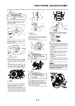
INSTALLING THE REAR BRAKE
MASTER CYLINDER
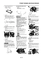
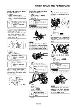
1. Install:
• Copper washer "1"
• Brake hose "2"
• Union bolt "3"
Always use new copper washers.
Install the brake hose so that its
pipe portion "a" directs as shown
and lightly touches the projection
"b" on the brake master cylinder.
2. Install:
• Brake master cylinder "1"
• Bolt (brake master cylinder) "2"
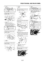
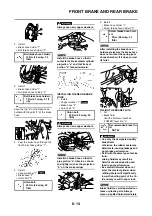
3. Install:
• Spring "1"
• Brake pedal "2"
• O-ring "3"
• Bolt (brake pedal) "4"
• Clip "5"
Apply the lithium soap base grease
on the bolt, O-ring and brake pedal
bracket.
4. Install:
• Pin "1"
• Washer "2"
• Cotter pin "3"
After installing, check the brake pedal
height. Refer to "ADJUSTING THE
REAR BRAKE" section in the CHAP-
TER 3.
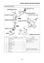
INSTALLING THE FRONT BRAKE
HOSE
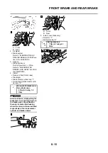
1. Install:
• Copper washer "1"
• Brake hose "2"
• Union bolt "3"
Always use new copper washers.
Install the brake hose so that its
pipe portion "a" directs as shown
and lightly touches the projection
"b" on the brake caliper.
Bolt (brake master cylin-
der bracket):
9 Nm (0.9 m•kg, 6.5
ft•lb)
Bolt (brake lever):
6 Nm (0.6 m•kg, 4.3
ft•lb)
Nut (brake lever):
6 Nm (0.6 m•kg, 4.3
ft•lb)
Union bolt:
30 Nm (3.0 m•kg, 22
ft•lb)
Bolt (brake master cylin-
der):
10 Nm (1.0 m•kg, 7.2
ft•lb)
Bolt (brake pedal):
26 Nm (2.6 m•kg, 19
ft•lb)
Union bolt:
30 Nm (3.0 m•kg, 22
ft•lb)
Summary of Contents for 2010 WR450FZ
Page 4: ......
Page 12: ...1 2 LOCATION OF IMPORTANT LABELS EUROPE ...
Page 13: ...1 3 LOCATION OF IMPORTANT LABELS AUS NZ ZA ...
Page 49: ...2 18 TIGHTENING TORQUES ...
Page 51: ...2 20 LUBRICATION DIAGRAMS 1 Intake camshaft 2 Exhaust camshaft A To main axle B From oil pump ...
Page 90: ...3 31 ELECTRICAL Charging method using a variable voltage charger ...
Page 91: ...3 32 ELECTRICAL Charging method using a constant voltage charger ...
Page 125: ...5 22 CYLINDER HEAD 3 Install Bolt cylinder head 1 Bolt cylinder head 10 Nm 1 0 m kg 7 2 ft lb ...
Page 144: ...5 41 OIL PUMP 15 Oil pump drive shaft 1 16 Rotor housing 1 Order Part name Q ty Remarks ...

