6-29
STEERING
HANDLING NOTE
Support the machine securely so
there is no danger of it falling over.
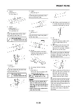
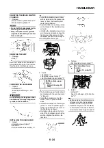
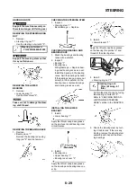
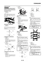
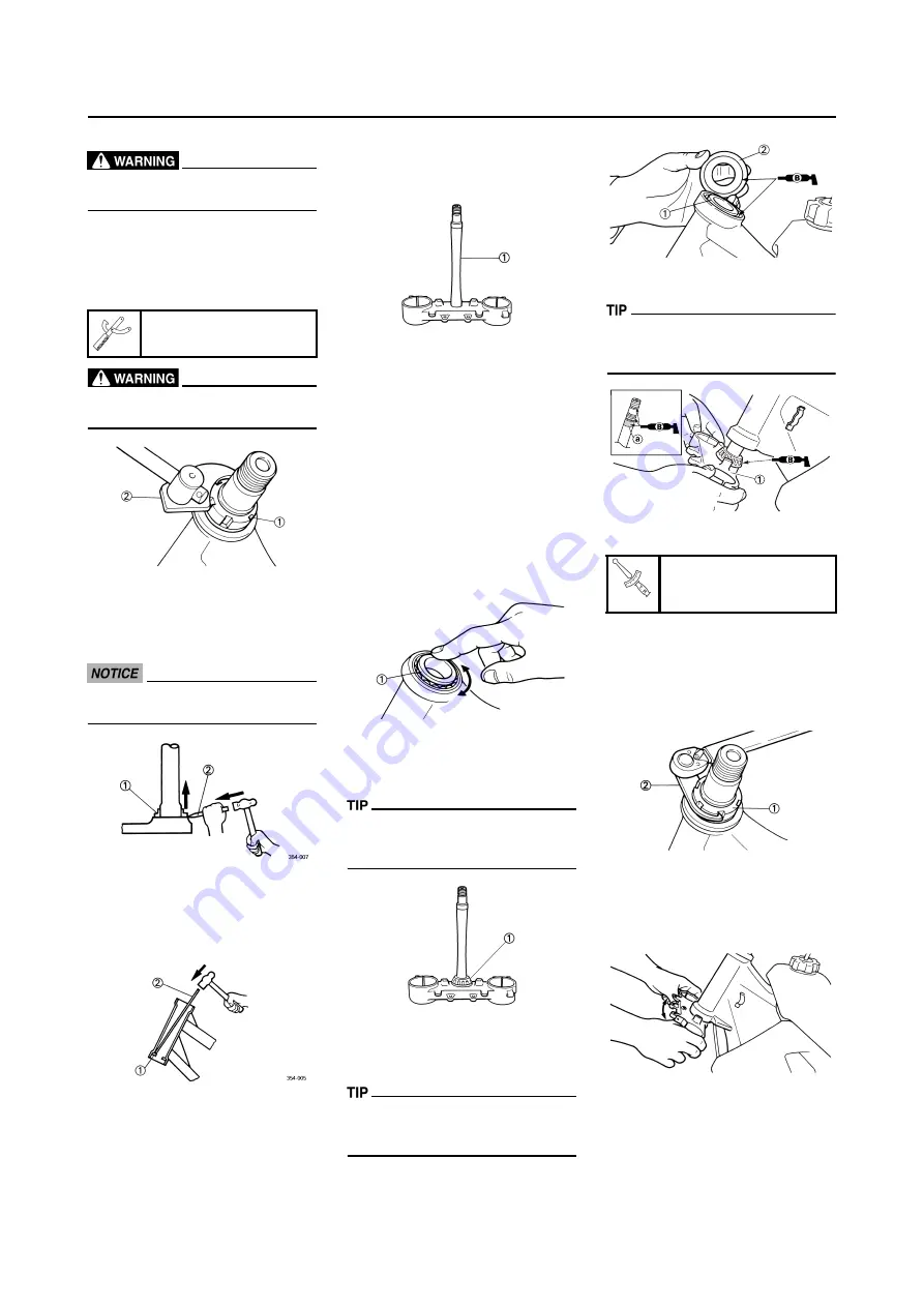
REMOVING THE STEERING RING
NUT
1. Remove:
• Steering ring nut "1"
Use the steering nut wrench "2".
Support the steering stem so that
it may not fall down.
REMOVING THE LOWER
BEARING
1. Remove:
• Lower bearing "1"
Use the floor chisel "2".
Take care not to damage the steer-
ing shaft thread.
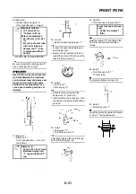
REMOVING THE BEARING RACE
1. Remove:
• Bearing race "1"
Remove the bearing race using
long rod "2" and the hammer.
CHECKING THE STEERING STEM
1. Inspect:
• Steering stem "1"
Bend/damage
→
Replace.
CHECKING THE BEARING AND
BEARING RACE
1. Wash the bearings and bearing
races with a solvent.
2. Inspect:
• Bearing "1"
• Bearing race
Pitting/damage
→
Replace bear-
ings and bearing races as a set.
Install the bearing in the bearing
races. Spin the bearings by hand.
If the bearings hang up or are not
smooth in their operation in the
bearing races, replace bearings
and bearing races as a set.
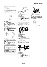
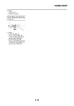
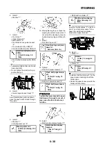
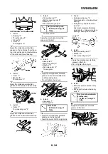
INSTALLING THE LOWER
BRACKET
1. Install:
• Lower bearing "1"
Apply the lithium soap base grease
on the dust seal lip and bearing inner
circumference.
2. Install:
• Bearing race
• Upper bearing "1"
• Bearing race cover "2"
Apply the lithium soap base grease
on the bearing and bearing race cov-
er lip.
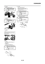
3. Install:
• Lower bracket "1"
Apply the lithium soap base grease
on the bearing, the portion "a" and
thread of the steering stem.
4. Install:
• Steering ring nut "1"
Tighten the steering ring nut using
the steering nut wrench "2".
Refer to "CHECKING AND AD-
JUSTING THE STEERING
HEAD" section in the CHAPTER
3.
5. Check the steering stem by turn-
ing it lock to lock. If there is any
binding, remove the steering stem
assembly and inspect the steer-
ing bearings.
Steering nut wrench:
YU-33975/90890-01403
Steering ring nut:
7 Nm (0.7 m•kg, 5.1
ft•lb)
Summary of Contents for 2010 WR450FZ
Page 4: ......
Page 12: ...1 2 LOCATION OF IMPORTANT LABELS EUROPE ...
Page 13: ...1 3 LOCATION OF IMPORTANT LABELS AUS NZ ZA ...
Page 49: ...2 18 TIGHTENING TORQUES ...
Page 51: ...2 20 LUBRICATION DIAGRAMS 1 Intake camshaft 2 Exhaust camshaft A To main axle B From oil pump ...
Page 90: ...3 31 ELECTRICAL Charging method using a variable voltage charger ...
Page 91: ...3 32 ELECTRICAL Charging method using a constant voltage charger ...
Page 125: ...5 22 CYLINDER HEAD 3 Install Bolt cylinder head 1 Bolt cylinder head 10 Nm 1 0 m kg 7 2 ft lb ...
Page 144: ...5 41 OIL PUMP 15 Oil pump drive shaft 1 16 Rotor housing 1 Order Part name Q ty Remarks ...

