7-1
ELECTRICAL COMPONENTS AND WIRING DIAGRAM
ELECTRICAL
This section is intended for those who have basic knowledge and skill concerning the servicing of Yamaha motorcycles
(e.g., Yamaha dealers, service engineers, etc.) Those who have little knowledge and skill concerning servicing are request-
ed not to undertake inspection, adjustment, disassembly, or reassembly only by reference to this manual. It may lead to
servicing trouble and mechanical damage.
ELECTRICAL COMPONENTS AND WIRING DIAGRAM
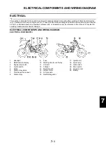
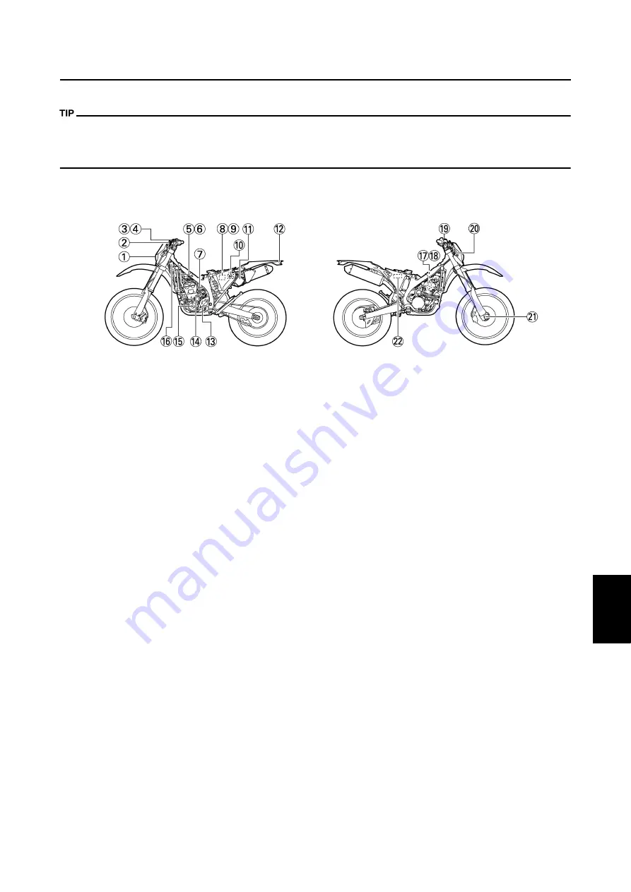
ELECTRICAL COMPONENTS
1.
Headlight
2.
Multi-function display
3.
Engine stop switch
4.
Clutch switch
5.
Diode
6.
Starter relay diode
7.
Throttle position sensor
8.
Starter relay
9.
Fuse
10. Starting circuit cut-off relay
11. CDI unit
12. Taillight
13. Neutral switch
14. Starter motor
15. AC magneto
16. Rectifier/regulator
17. Ignition coil
18. Spark plug
19. Start switch
20. Main switch
21. Speed sensor
22. Battery
7
Summary of Contents for 2010 WR450FZ
Page 4: ......
Page 12: ...1 2 LOCATION OF IMPORTANT LABELS EUROPE ...
Page 13: ...1 3 LOCATION OF IMPORTANT LABELS AUS NZ ZA ...
Page 49: ...2 18 TIGHTENING TORQUES ...
Page 51: ...2 20 LUBRICATION DIAGRAMS 1 Intake camshaft 2 Exhaust camshaft A To main axle B From oil pump ...
Page 90: ...3 31 ELECTRICAL Charging method using a variable voltage charger ...
Page 91: ...3 32 ELECTRICAL Charging method using a constant voltage charger ...
Page 125: ...5 22 CYLINDER HEAD 3 Install Bolt cylinder head 1 Bolt cylinder head 10 Nm 1 0 m kg 7 2 ft lb ...
Page 144: ...5 41 OIL PUMP 15 Oil pump drive shaft 1 16 Rotor housing 1 Order Part name Q ty Remarks ...

