1-15
MULTI-FUNCTION DISPLAY
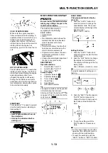
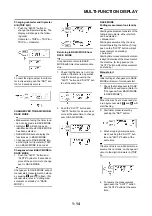
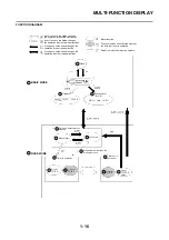
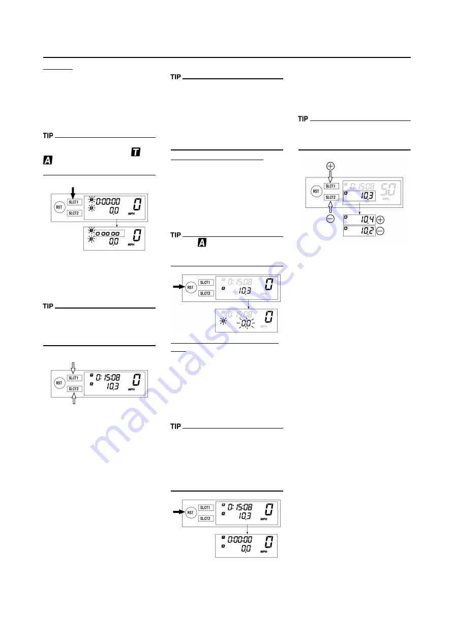
Auto start
1. Check that changeover has been
made to RACE MODE. (Refer to
"Changeover from BASIC MODE
to RACE MODE".)
2. Make the machine ready for a run
by pushing the "SLCT1" button for
2 seconds or more.
When the measurement is made
ready for a run by auto start,
and
will start flashing. Timer display
will turn on scrolling from left to right.
3. Run the machine and start timer
measurement.
4. To stop timer measurement,
pushing the "SLCT1" button and
"SLCT2" button at the same time.
If the machine is run while timer mea-
surement is not made, no change will
occur to the digit in tripmeter A (TRIP
A).
5. To resume the measurement,
again pushing the "SLCT1" button
and "SLCT2" button at the same
time.
Resetting measurement data
Resetting can be made in the follow-
ing two manners.
Resetting is possible while timer
measurement is made:
• Reset tripmeter A.
Resetting is possible while timer
measurement is not made:
• Reset tripmeter A and timer.
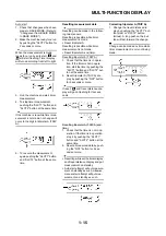
Resetting tripmeter A (TRIP A)
1. Check that the timer is in opera-
tion. If the timer is not in opera-
tion, start the timer by pushing the
"SLCT1" button and "SLCT2" but-
ton at the same time.
2. Reset tripmeter A (TRIP A) dis-
play by pushing the "RST" button
for 2 seconds or more.
If reset,
and travel distance dis-
play will go on flashing for four sec-
onds.
Resetting tripmeter A (TRIP A) and
timer
1. Check that the timer is not in op-
eration. If the timer is in operation,
stop it by pushing the "SLCT1"
button and "SLCT2" button at the
same time.
2. Reset all measured data by push-
ing the "RST" button for 2 sec-
onds or more.
• Resetting will reset the timer display
and travel distance display and put
measurement on standby.
• Auto start attempt will put measure-
ment on standby as such. Likewise,
manual start attempt will put mea-
surement on standby as such.
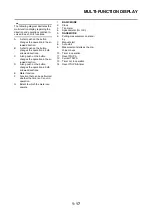
Correcting tripmeter A (TRIP A)
1. Change the travel distance dis-
play by pushing the "SLCT1" but-
ton (plus) or "SLCT2" button
(minus). A long push on the but-
ton will fast-forward the change.
Change can be made any time while
timer measurement is or is not being
made.
Summary of Contents for 2010 WR450FZ
Page 4: ......
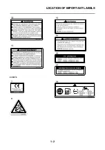
Page 12: ...1 2 LOCATION OF IMPORTANT LABELS EUROPE ...
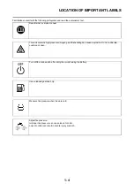
Page 13: ...1 3 LOCATION OF IMPORTANT LABELS AUS NZ ZA ...
Page 49: ...2 18 TIGHTENING TORQUES ...
Page 51: ...2 20 LUBRICATION DIAGRAMS 1 Intake camshaft 2 Exhaust camshaft A To main axle B From oil pump ...
Page 90: ...3 31 ELECTRICAL Charging method using a variable voltage charger ...
Page 91: ...3 32 ELECTRICAL Charging method using a constant voltage charger ...
Page 125: ...5 22 CYLINDER HEAD 3 Install Bolt cylinder head 1 Bolt cylinder head 10 Nm 1 0 m kg 7 2 ft lb ...
Page 144: ...5 41 OIL PUMP 15 Oil pump drive shaft 1 16 Rotor housing 1 Order Part name Q ty Remarks ...

