2-14
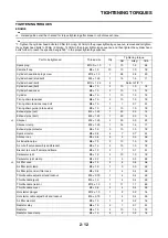
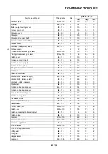
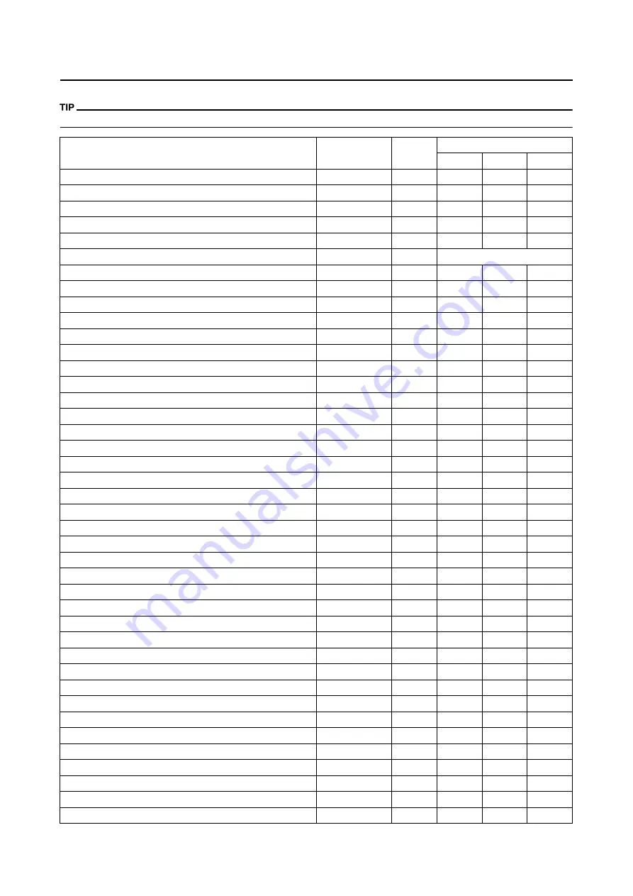
TIGHTENING TORQUES
CHASSIS
△
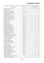
- marked portion shall be checked for torque tightening after break-in or before each race.
Part to be tightened
Thread size
Q'ty
Tightening torque
Nm
m•kg
ft•lb
△
Upper bracket and outer tube
M8 × 1.25
4
21
2.1
15
△
Lower bracket and outer tube
M8 × 1.25
4
21
2.1
15
△
Upper bracket and steering stem
M24 × 1.0
1
145
14.5
105
△
Handlebar holder (upper)
M8 × 1.25
4
28
2.8
20
△
Handlebar holder (lower)
M12 × 1.25
2
34
3.4
24
△
Steering ring nut
M28 × 1.0
1
Refer to TIP.
Front fork and cap bolt
M51 × 1.5
2
30
3.0
22
Front fork and base valve
M30 × 1.0
2
55
5.5
40
Cap bolt and damper rod (front fork)
M12 × 1.25
2
29
2.9
21
Bleed screw (front fork) and cap bolt
M5 × 0.8
2
1
0.1
0.7
△
Front fork and protector
M6 × 1.0
6
7
0.7
5.1
△
Front fork protector and brake hose holder
M6 × 1.0
2
7
0.7
5.1
Throttle cable cap
M5 × 0.8
2
4
0.4
2.9
Clutch lever holder mounting
M5 × 0.8
2
4
0.4
2.9
Clutch lever mounting
M6 × 1.0
1
4
0.4
2.9
Hot starter lever holder mounting
M5 × 0.8
2
4
0.4
2.9
Hot starter lever mounting
M5 × 0.8
1
2
0.2
1.4
△
Front brake master cylinder and bracket
M6 × 1.0
2
9
0.9
6.5
Front brake master cylinder cap
M4 × 0.7
2
2
0.2
1.4
Brake lever mounting (bolt)
M6 × 1.0
1
6
0.6
4.3
Brake lever mounting (nut)
M6 × 1.0
1
6
0.6
4.3
Brake lever position locknut
M6 × 1.0
1
5
0.5
3.6
△
Hose guide (front brake hose) and hose guide bracket
M5 × 0.8
1
4
0.4
2.9
△
Hose guide (front brake hose) and under bracket
M6 ×1.0
1
4
0.4
2.9
△
Front brake hose union bolt (master cylinder)
M10 × 1.25
1
30
3.0
22
△
Front brake hose union bolt (caliper)
M10 × 1.25
1
30
3.0
22
△
Front brake caliper and front fork
M8 × 1.25
2
23
2.3
17
△
Front brake caliper and brake hose holder
M6 × 1.0
1
10
1.0
7.2
△
Brake caliper (front and rear) and pad pin plug
M10 × 1.0
2
3
0.3
2.2
△
Brake caliper (front and rear) and pad pin
M10 × 1.0
2
18
1.8
13
△
Brake caliper (front and rear) and bleed screw
M8 × 1.25
2
6
0.6
4.3
△
Front wheel axle and nut
M16 × 1.5
1
90
9.0
65
△
Front wheel axle holder
M8 × 1.25
4
21
2.1
15
△
Front brake disc and wheel hub
M6 × 1.0
6
12
1.2
8.7
△
Rear brake disc and wheel hub
M6 × 1.0
6
14
1.4
10
△
Brake pedal mounting
M8 × 1.25
1
26
2.6
19
△
Rear brake master cylinder and frame
M6 × 1.0
2
10
1.0
7.2
Rear brake master cylinder cap
M4 × 0.7
2
2
0.2
1.4
△
Rear brake hose union bolt (caliper)
M10 × 1.25
1
30
3.0
22
△
Rear brake hose union bolt (master cylinder)
M10 × 1.25
1
30
3.0
22
△
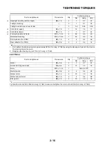
Rear wheel axle and nut
M20 × 1.5
1
125
12.5
90
Summary of Contents for 2010 WR450FZ
Page 4: ......
Page 12: ...1 2 LOCATION OF IMPORTANT LABELS EUROPE ...
Page 13: ...1 3 LOCATION OF IMPORTANT LABELS AUS NZ ZA ...
Page 49: ...2 18 TIGHTENING TORQUES ...
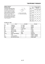
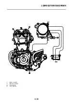
Page 51: ...2 20 LUBRICATION DIAGRAMS 1 Intake camshaft 2 Exhaust camshaft A To main axle B From oil pump ...
Page 90: ...3 31 ELECTRICAL Charging method using a variable voltage charger ...
Page 91: ...3 32 ELECTRICAL Charging method using a constant voltage charger ...
Page 125: ...5 22 CYLINDER HEAD 3 Install Bolt cylinder head 1 Bolt cylinder head 10 Nm 1 0 m kg 7 2 ft lb ...
Page 144: ...5 41 OIL PUMP 15 Oil pump drive shaft 1 16 Rotor housing 1 Order Part name Q ty Remarks ...

