CAMSHAFTS
5-15
EBS30433
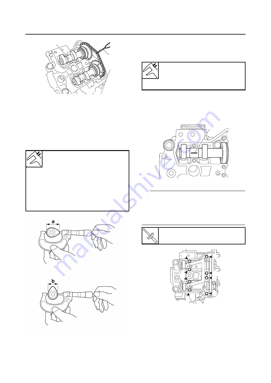
CHECKING THE CAMSHAFTS
1. Check:
• Camshaft lobes
Blue discoloration/pitting/scratches
→
Re-
place the camshaft.
2. Measure:
• Camshaft lobe dimensions “a” and “b”
Out of specification
→
Replace the camshaft.
3. Measure:
• Camshaft-journal-to-camshaft-cap clearance
Out of specification
→
Measure the camshaft
journal diameter.
▼▼▼
▼
▼ ▼▼▼
▼
▼ ▼▼▼
▼
▼ ▼▼▼
▼
▼ ▼▼▼
▼
▼ ▼▼▼
▼
▼▼▼
a. Install the camshafts into the cylinder head
(without the camshaft cap).
b. Position a strip of Plastigauge® “1” onto the
camshaft journal as shown.
c. Install the camshaft cap.
TIP
• Tighten the camshaft cap bolts in the tighten-
ing sequence as shown.
• Do not turn the camshaft when measuring the
camshaft journal-to-camshaft cap clearance
with the Plastigauge®.
d. Remove the camshaft cap, and then mea-
sure the width of the Plastigauge® “1”.
Camshaft lobe dimensions
Lobe height (Intake) limit
33.800 mm (1.3307 in)
Base circle diameter (Intake) limit
24.850 mm (0.9783 in)
Lobe height (Exhaust) limit
30.750 mm (1.2106 in)
Base circle diameter (Exhaust)
limit
22.350 mm (0.8799 in)
1
3
2
Camshaft-journal-to-camshaft-
cap clearance
0.037–0.075 mm (0.0015–0.0030
in)
T
R
.
.
Camshaft cap bolt
10 Nm (1.0 m·kgf, 7.2 ft·lbf)
1
5
7
8
4
3
1
2
6
Summary of Contents for 2016 Grizzly yf700gg
Page 6: ......
Page 8: ......
Page 11: ...IDENTIFICATION 1 2 ...
Page 37: ...ENGINE SPECIFICATIONS 2 6 Air induction system Solenoid resistance 18 22 Ω ...
Page 58: ...LUBRICATION SYSTEM CHART AND DIAGRAMS 2 27 EBS30023 LUBRICATION DIAGRAMS 6 7 8 9 3 4 3 2 1 5 ...
Page 60: ...LUBRICATION SYSTEM CHART AND DIAGRAMS 2 29 1 2 3 4 5 ...
Page 62: ...COOLING SYSTEM DIAGRAMS 2 31 EBS20021 COOLING SYSTEM DIAGRAMS 1 2 3 10 9 8 6 7 5 4 ...
Page 78: ...CABLE ROUTING 2 47 Front and rear brake hoses F 3 F 3 F 3 3 I G H 4 4 B C D 2 E D 2 A 1 ...
Page 80: ...CABLE ROUTING 2 49 ...
Page 83: ......
Page 119: ...PERIODIC MAINTENANCE 3 36 A Headlight left and right B Handle mounted light b a 1 A b a 1 B ...
Page 120: ...PERIODIC MAINTENANCE 3 37 ...
Page 197: ...REAR ARMS AND REAR SHOCK ABSORBER ASSEMBLIES 4 74 7 9 8 9 7 3 5 4 5 3 6 2 10 10 1 ...
Page 198: ...REAR ARMS AND REAR SHOCK ABSORBER ASSEMBLIES 4 75 ...
Page 203: ...ENGINE INSPECTION 5 2 Top cover Refer to GENERAL CHASSIS 2 on page 4 6 ...
Page 244: ...ELECTRIC STARTER 5 43 a b b 1 2 3 ...
Page 316: ...AIR INDUCTION SYSTEM 7 9 EBS20057 AIR INDUCTION SYSTEM 3 4 1 2 3 4 1 2 ...
Page 352: ...REAR CONSTANT VELOCITY SHAFT ASSEMBLIES FINAL DRIVE ASSEMBLY AND REAR DRIVE SHAFT 8 31 ...
Page 355: ......
Page 365: ...ELECTRIC STARTING SYSTEM 9 10 ...
Page 369: ...CHARGING SYSTEM 9 14 ...
Page 417: ...FUEL PUMP SYSTEM 9 62 ...
Page 434: ...ELECTRICAL COMPONENTS 9 79 1 2 3 5 7 8 9 10 11 12 13 14 15 16 17 18 19 4 6 ...
Page 454: ...ELECTRICAL COMPONENTS 9 99 ...
Page 468: ......
Page 469: ......
Page 470: ......


