TRANSMISSION
5-79
EBS30198
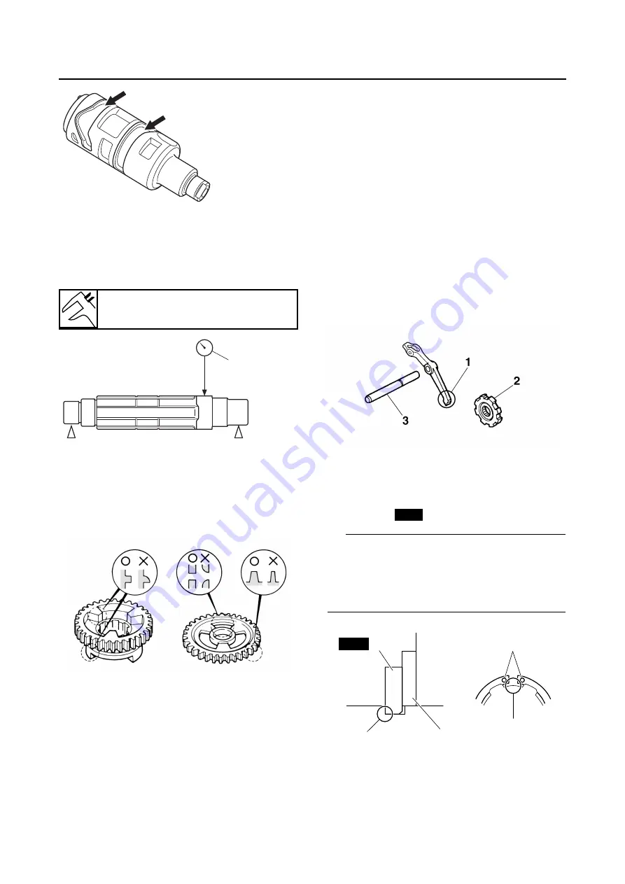
CHECKING THE TRANSMISSION
1. Measure:
• Drive axle runout
(with a centering device and dial gauge “1”)
Out of specification
→
Replace the drive axle.
2. Check:
• Transmission gears
Blue discoloration/pitting/wear
→
Replace
the defective gear(s).
• Transmission gear dogs
Cracks/damage/rounded edges
→
Replace
the defective gear(s).
3. Check:
• Transmission gear engagement
(each pinion gear to its respective wheel
gear)
Incorrect
→
Reassemble the transmission
axle assemblies.
4. Check:
• Transmission gear movement
Rough movement
→
Replace the defective
part(s).
EBS30199
CHECKING THE SECONDARY SHAFT
1. Check:
• Gear teeth
Blue discoloration/pitting/wear
→
Replace.
EBS30555
CHECKING THE STOPPER LEVER AND
STOPPER WHEEL
1. Check:
• Stopper lever pawl “1”
Bends/damage/wear
→
Replace the stopper
lever and stopper wheel as a set.
• Stopper wheel “2”
Damage/wear
→
Replace the stopper wheel
and stopper lever as a set.
• Stopper lever shaft “3”
Bends/damage/wear
→
Replace.
EBS30200
ASSEMBLING THE DRIVE AXLE
1. Install:
• Washer “1”
• Circlip “2”
TIP
• Be sure the circlip sharp-edged corner “a” is
positioned opposite side to the washer and
gear.
• Be sure the circlip ends “b” are positioned at
axle spline groove “c”.
EBS30201
ASSEMBLING THE SHIFT FORK
1. Install:
• Shift fork guide bar “1”
Drive axle runout limit
0.06 mm (0.0024 in)
1
New
a
1
c
b
2
New
Summary of Contents for 2016 Grizzly yf700gg
Page 6: ......
Page 8: ......
Page 11: ...IDENTIFICATION 1 2 ...
Page 37: ...ENGINE SPECIFICATIONS 2 6 Air induction system Solenoid resistance 18 22 Ω ...
Page 58: ...LUBRICATION SYSTEM CHART AND DIAGRAMS 2 27 EBS30023 LUBRICATION DIAGRAMS 6 7 8 9 3 4 3 2 1 5 ...
Page 60: ...LUBRICATION SYSTEM CHART AND DIAGRAMS 2 29 1 2 3 4 5 ...
Page 62: ...COOLING SYSTEM DIAGRAMS 2 31 EBS20021 COOLING SYSTEM DIAGRAMS 1 2 3 10 9 8 6 7 5 4 ...
Page 78: ...CABLE ROUTING 2 47 Front and rear brake hoses F 3 F 3 F 3 3 I G H 4 4 B C D 2 E D 2 A 1 ...
Page 80: ...CABLE ROUTING 2 49 ...
Page 83: ......
Page 119: ...PERIODIC MAINTENANCE 3 36 A Headlight left and right B Handle mounted light b a 1 A b a 1 B ...
Page 120: ...PERIODIC MAINTENANCE 3 37 ...
Page 197: ...REAR ARMS AND REAR SHOCK ABSORBER ASSEMBLIES 4 74 7 9 8 9 7 3 5 4 5 3 6 2 10 10 1 ...
Page 198: ...REAR ARMS AND REAR SHOCK ABSORBER ASSEMBLIES 4 75 ...
Page 203: ...ENGINE INSPECTION 5 2 Top cover Refer to GENERAL CHASSIS 2 on page 4 6 ...
Page 244: ...ELECTRIC STARTER 5 43 a b b 1 2 3 ...
Page 316: ...AIR INDUCTION SYSTEM 7 9 EBS20057 AIR INDUCTION SYSTEM 3 4 1 2 3 4 1 2 ...
Page 352: ...REAR CONSTANT VELOCITY SHAFT ASSEMBLIES FINAL DRIVE ASSEMBLY AND REAR DRIVE SHAFT 8 31 ...
Page 355: ......
Page 365: ...ELECTRIC STARTING SYSTEM 9 10 ...
Page 369: ...CHARGING SYSTEM 9 14 ...
Page 417: ...FUEL PUMP SYSTEM 9 62 ...
Page 434: ...ELECTRICAL COMPONENTS 9 79 1 2 3 5 7 8 9 10 11 12 13 14 15 16 17 18 19 4 6 ...
Page 454: ...ELECTRICAL COMPONENTS 9 99 ...
Page 468: ......
Page 469: ......
Page 470: ......


