3 - 9
CHK
ADJ
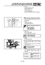
ADJUSTING THE VALVE CLEARANCE
NOTE:
_
• When the piston is at the Top Dead Center
(TDC) on the compression stroke, there
should be clearance between the valve stem
tips and their respective adjusting screws.
• Be sure to align the alignment mark
3
on the
camshaft sprocket with the alignment mark
4
on the cylinder head.
• If there is no clearance, rotate the crankshaft
counterclockwise one turn.
c. Measure the valve clearance using a thick-
ness gauge
5
.
▲▲▲
▲
▲ ▲▲▲
▲
▲ ▲▲▲
▲
▲ ▲▲▲
▲
▲ ▲▲▲
▲
▲ ▲▲▲
▲
▲▲▲
3. Adjust:
• valve clearance
▼▼▼
▼
▼ ▼▼▼
▼
▼ ▼▼▼
▼
▼ ▼▼▼
▼
▼ ▼▼▼
▼
▼ ▼▼▼
▼
▼▼▼
a. Loosen the locknut
1
.
b. Insert a thickness gauge
2
between the
adjuster end and the valve end.
c. Turn the adjuster
3
clockwise or counter-
clockwise with the tappet adjusting tool
4
until the proper clearance is obtained.
d. Hold the adjuster to prevent it from moving
and then tighten the locknut.
e. Measure the valve clearance.
f. If the clearance is incorrect, repeat the
above steps until the proper clearance is
obtained.
▲▲▲
▲
▲ ▲▲▲
▲
▲ ▲▲▲
▲
▲ ▲▲▲
▲
▲ ▲▲▲
▲
▲ ▲▲▲
▲
▲▲▲
Tappet adjusting tool (3 mm)
P/N. YM-08035, 90890-01311
T
R
.
.
Locknut
7 Nm (0.7 m · kg, 5.1 ft · lb)
Summary of Contents for 5YF2-AE1
Page 1: ...YFM50S5YF2 AE1 SERVICE MANUAL ...
Page 2: ......
Page 8: ......
Page 9: ...GEN INFO 1 ...
Page 11: ...GEN INFO ...
Page 20: ...SPEC 2 ...
Page 22: ...SPEC ...
Page 44: ...2 22 SPEC OIL FLOW DIAGRAMS 1 Oil pump 2 Oil strainer ...
Page 53: ...CHK ADJ 3 ...
Page 55: ...CHK ADJ ...
Page 94: ...ENG 4 ...
Page 163: ...CARB 5 ...
Page 165: ...CARB ...
Page 172: ...DRIV 6 ...
Page 174: ...DRIV ...
Page 188: ......
Page 189: ...CHAS 7 ...
Page 220: ...ELEC 8 ...
Page 222: ... ELEC ...
Page 250: ......
Page 251: ...TRBL SHTG 9 ...
Page 253: ...TRBL SHTG ...
Page 259: ......
Page 260: ......
Page 261: ...YAMAHA MOTOR CO LTD 2500 SHINGAI IWATA SHIZUOKA JAPAN ...


