3 - 28
CHK
ADJ
ADJUSTING THE TOE-IN/CHECKING THE FRONT AND
REAR SHOCK ABSORBERS
▼▼▼
▼
▼ ▼▼▼
▼
▼ ▼▼▼
▼
▼ ▼▼▼
▼
▼ ▼▼▼
▼
▼ ▼▼▼
▼
▼▼▼
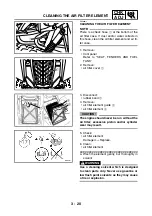
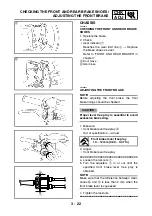
a. Mark both tie-rods ends.
This reference point will be needed during
adjustment.
b. Loosen the locknuts (tie-rod end)
1
of both
tie-rods.
c. The same number of turns should be given
to both the right and left tie-rods
2
until the
specified toe-in is obtained. This is to keep
the length of the rods the same.
d. Tighten the rod end locknuts of both tie-
rods.
NOTE:
_
Adjust the rod ends so that A and B are equal.
▲▲▲
▲
▲ ▲▲▲
▲
▲ ▲▲▲
▲
▲ ▲▲▲
▲
▲ ▲▲▲
▲
▲ ▲▲▲
▲
▲▲▲
EBS00109
CHECKING THE FRONT AND REAR SHOCK
ABSORBERS
1. Place the machine on a level surface.
2. Check:
• damper rod
1
Scratch/damage
→
Replace as a set.
• oil leakage
Excessive oil leakage
→
Replace as a set.
Refer to “FRONT SHOCK ABSORBER
ASSEMBLIES AND FRONT SWINGARM”
and “REAR SHOCK ABSORBER AND
REAR SWINGARM” in chapter 7.
3. Check:
• operation
Pump the shock absorbers up and down for
several times.
Unsmooth operation
→
Replace as a set.
Refer to “FRONT SHOCK ABSORBER
ASSEMBLIES AND FRONT SWINGARM”
and “REAR SHOCK ABSORBER AND
REAR SWINGARM” in chapter 7.
È
Front shock absorber
É
Rear shock absorber
T
R
.
.
Locknut (rod end)
15 Nm (1.5 m · kg, 11 ft · lb)
È
É
Summary of Contents for 5YF2-AE1
Page 1: ...YFM50S5YF2 AE1 SERVICE MANUAL ...
Page 2: ......
Page 8: ......
Page 9: ...GEN INFO 1 ...
Page 11: ...GEN INFO ...
Page 20: ...SPEC 2 ...
Page 22: ...SPEC ...
Page 44: ...2 22 SPEC OIL FLOW DIAGRAMS 1 Oil pump 2 Oil strainer ...
Page 53: ...CHK ADJ 3 ...
Page 55: ...CHK ADJ ...
Page 94: ...ENG 4 ...
Page 163: ...CARB 5 ...
Page 165: ...CARB ...
Page 172: ...DRIV 6 ...
Page 174: ...DRIV ...
Page 188: ......
Page 189: ...CHAS 7 ...
Page 220: ...ELEC 8 ...
Page 222: ... ELEC ...
Page 250: ......
Page 251: ...TRBL SHTG 9 ...
Page 253: ...TRBL SHTG ...
Page 259: ......
Page 260: ......
Page 261: ...YAMAHA MOTOR CO LTD 2500 SHINGAI IWATA SHIZUOKA JAPAN ...

