background image

18

 En

Refer to the chart below when this unit does not function properly. If the problem you are experiencing is not listed below 
or if the instructions given below do not help, disconnect the power cord and contact your authorized Yamaha dealer or 
service center.

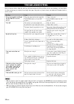
• When an excessive level of signal is input to this unit for 5 to 15 minutes, the POWER indicator starts flashing to alarm 

you of the danger of damaging the power amplifier and speaker of this unit. If the signal input lasts for 5 minutes more, 
this unit turns into the standby mode automatically.

• When an enormous amount of signal is input, the power of this unit is turned off immediately. To turn on this unit again, 

press STANDBY/ON switch on the front panel.

TROUBLESHOOTING

Problem

Cause

Remedy

Power is not supplied even though 
the STANDBY/ON switch is 
pressed.

The power plug is not securely connected. 

Connect it securely.

The POWER switch is set to the OFF 
position.

Set the POWER switch to the ON 
position.

No sound.

The volume is set to the minimum (0).

Raise the volume.

Speaker cables are not connected securely.

Connect them securely.

The signals from the amplifier are too low.

Increase the volume of the amplifier or the 
component connected to the amplifier.

The signal from the subwoofer output 
terminal of the amplifier is not output.

Check the speaker mode setting on the 
amplifier.

Sound level is too low.

Speaker cables are not connected correctly.

Connect them correctly, that is L (left) to 
L, R (right) to R, “+” to “+” and 
“–” to “–”.

Setting of the phase is not proper.

Set the phase to the other position.

A source sound with few bass frequencies is 
being played.

Play a source sound with bass 
frequencies.
Set the H-CUT to a higher position.

It is influenced by standing waves.

Reposition this unit or break up the 
parallel surface by placing bookshelves 
etc. along the walls.

The remote control does not 
work.

Wrong distance or angle.

Use the remote control within a maximum 
range of 6 m and no more then 30 degrees 
off-axis from the front panel.

Direct sunlight or lighting from an inverter 
type of fluorescent lamp etc. is striking the 
remote control sensor of this unit.

Reposition this unit.

The batteries are weak.

Replace all batteries.

This unit is not turned on with the 
remote control of the amplifier. 
(when setting “Operating the 
power of this unit using the 
remote control of your 
amplifier”)

Wrong distance or angle.

Place this unit within the operating range 
of the remote control of the amplifier.

The household breaker goes off.

This unit consumes much electricity when a 
high level signal is input to this unit.

Turn down the volume on the amplifier 
etc. connected to this unit or cut off the 
power of other unused equipment.

Notes

Summary of Contents for 900SW

Page 1: ...Soavo 900SW SUBWOOFER SYSTEM UB OWNER S MANUAL ...

Page 2: ...ng lightning storms or when unused for long periods of time 14 Refer all servicing to qualified service personnel Servicing is required when the apparatus has been damaged in any way such as power supply cord or plug is damaged liquid has been spilled or objects have fallen into the apparatus the apparatus has been exposed to rain or moisture does not operate normally or has been dropped IMPORTANT...

Page 3: ... for Class B digital devices Compliance with these requirements provides a reasonable level of assurance that your use of this product in a residential environment will not result in harmful interference with other electronic devices This equipment generates uses radio frequencies and if not installed and used according to the instructions found in the users manual may cause interference harmful t...

Page 4: ...do not hold the port as it might cause personal injury and or damage to this unit 13 Never place a fragile object near the YST port of this unit If the object falls or drops by the air pressure it may cause damage to the unit and or personal injury 14 Never open the cabinet It might cause an electric shock since this unit uses a high voltage It might also cause personal injury and or damage to thi...

Page 5: ...al 9 Connecting to the ground terminal 12 Connecting the power cable 12 USING THIS UNIT 13 Adjusting the sound balance 13 Storing the sound balance settings 14 Setting the sleep timer 14 Operating the power of this unit using the remote control of your amplifier 15 Frequency response 16 Advanced Yamaha Active Servo Technology II 17 TROUBLESHOOTING 18 SPECIFICATIONS 19 IMPORTANT THE WIRES IN MAINS ...

Page 6: ...ss sounds with various settings Setting high cut and phase keeps the optimum sound quality balance between the front speakers and this unit B A S S mode button This unit is equipped with the B A S S mode button so that you can enjoy bass sound that matches any kind of source In this manual operations that can be performed using either the front panel of this unit or the remote control are explaine...

Page 7: ...UME control Adjusts the volume level Turn the control clockwise to increase the volume counterclockwise to decrease the volume 7 B A S S indicators Light up to indicate the currently selected B A S S number 1 2 or 3 see page 13 8 PRESET indicators Light up to indicate the currently selected PRESET number 1 2 or 3 see page 14 If you set this unit to the standby mode when one of the PRESET indicator...

Page 8: ...or the source Each time you press B A S S the B A S S indicator changes between 1 2 and 3 4 PRESET Stores or recalls the B A S S volume high cut frequency and phase settings see page 14 5 HIGH CUT Adjusts the high frequency cut off point depending on the connected front speakers or your preference see page 13 6 SLEEP Sets the sleep timer see page 14 7 PHASE Switches the phase mode Normally set thi...

Page 9: ...om the remote control to prevent an explosion or acid leak Dispose of the batteries according to the regional regulations If a battery starts leaking dispose of it immediately Be careful not to let leaking battery acid come into contact with your skin or clothing Before inserting new batteries wipe the compartment clean Using the remote control The remote control transmits a directional infrared r...

Page 10: ...sing one subwoofer Place the subwoofer on the outside of either the right or the left front speaker y If the subwoofer is placed directly facing the wall the bass sound may lessen because the sound from the subwoofer and the sound reflected by the wall may cancel each other out To prevent this from happening face the subwoofer obliquely to the wall or When using two subwoofers Place the subwoofers...

Page 11: ...d R side subwoofer terminal of your amplifier to the INPUT 3 terminal of this unit using a commercially available audio pin cable Some amplifiers have line output terminals labeled PRE OUT When you connect this unit to the PRE OUT terminals of the amplifier make sure that the amplifier has at least two sets of PRE OUT terminals If the amplifier has only one set of PRE OUT terminals do not connect ...

Page 12: ... high cut function If your amplifier can cut off high frequencies from the signals for sending to the subwoofer connect the amplifier to the INPUT 2 LFE terminal of this unit This brings you higher sound quality because the signal routing in this unit is shortened by bypassing the built in HIGH CUT high cut circuit R L OUTPUT TO SPEAKERS FROM AMPLIFIER L L L R R R L R MONO OUTPUT TO SPEAKERS FROM ...

Page 13: ...let the bare speaker wires touch each other because this could damage this unit or the amplifier or both of them For connection keep the speaker cables as short as possible Do not bundle or roll up the excess part of the cables If the connections are faulty no sound will be heard from this unit or the speakers or both of them Make sure that the and polarity markings of the speaker terminals are ob...

Page 14: ...affect the sound quality Using one subwoofer Using two subwoofers OUTPUT TO SPEAKERS FROM AMPLIFIER L L L R R R L R MONO INPUT 3 INPUT 2 INPUT 1 Front speaker R Front speaker L Speaker terminals Amplifier Subwoofer OUTPUT TO SPEAKERS FROM AMPLIFIER INPUT 3 INPUT 2 L L L R R R L R MONO OUTPUT TO SPEAKERS FROM AMPLIFIER L L L R R R L R MONO OUTPUT TO SPEAKERS FROM AMPLIFIER L L L R R R L R MONO INPU...

Page 15: ...t sound signals simultaneously When your amplifier cannot output sound signals simultaneously even if you connect in this way follow When your amplifier has one set of front speaker terminals on page 10 Using one subwoofer Using two subwoofers Note OUTPUT TO SPEAKERS FROM AMPLIFIER L L L R R R L R MONO INPUT 3 INPUT 2 INPUT 1 Front speaker R Front speaker L Speaker terminals Amplifier Subwoofer OU...

Page 16: ...the amplifier and this unit are not plugged into the AC outlet Plug the supplied power cable into the AC IN of this unit after all other connections are complete and then plug the power cable to an AC outlet Do not use other power cables Use the provided cable Use of other power cables may result in fire hazard or electrical shock Do not plug the power cable into the AC outlet of your amplifier Do...

Page 17: ...ont speaker refer to the owner s manual of the front speaker 6 Press VOLUME to increase the volume gradually to adjust the volume balance between the front speaker and this unit Normally set the volume to a level where you can obtain a little more bass effect than when this unit is not used y If you cannot obtain the desired response repeat steps 5 and 6 7 Press PHASE to select the regular or reve...

Page 18: ...or 3 Memory back up Even if you turn off this unit by using the POWER switch on the rear panel this unit recalls the last setting when the power is turned back on Last memory function If the power is cut for more than one week the setting is cleared If you set the sleep timer this unit automatically turns to the standby mode after 120 minutes Press SLEEP The color of the STANDBY ON indicator chang...

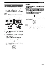
Page 19: ...ng is completed Canceling 1 Set POWER switch on the rear panel to the OFF position 2 Set POWER switch to the ON position while pressing and holding STANDBY ON switch on the front panel Continue holding down STANDBY ON switch for 3 seconds or longer After the STANDBY ON indicator flashes 2 times the setting is completed Place this unit within the operating range of the remote control of the amplifi...

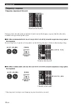
Page 20: ...cm or 25 cm 7 14 16 or 9 13 16 acoustic suspension 2 way system front speakers These diagrams do not depict actual frequency response characteristics accurately Frequency response reverse mode Green reverse mode Green 20 50 100 200 500Hz 40 50 60 70 80 90 dB H CUT 140 Hz Frequency response graph H CUT 1 4 0 H z 4 0 H z VOLUME 10 0 H CUT VOLUME OOFER SYSTEM S PHASE 1 PHASE 20 50 100 200 500Hz 40 50...

Page 21: ...is allows for bass reproduction from much smaller cabinets than was previously possible Yamaha s newly developed Advanced YST II adds many refinements to Yamaha Active Servo Technology allowing better control of the forces driving the amplifier and speaker From the amplifier s point of view the speaker impedance changes depending on the sound frequency Yamaha developed a new circuit design combini...

Page 22: ... the subwoofer output terminal of the amplifier is not output Check the speaker mode setting on the amplifier Sound level is too low Speaker cables are not connected correctly Connect them correctly that is L left to L R right to R to and to Setting of the phase is not proper Set the phase to the other position A source sound with few bass frequencies is being played Play a source sound with bass ...

Page 23: ...20 V 60 Hz U K and Europe models AC 230 V 50 Hz Australia model AC 240 V 50 Hz Asia and General models AC 110 120 220 230 240 V 50 60 Hz Korea model AC 220 V 60 Hz China model AC 220 V 50 Hz Power Consumption 180 W Standby Power Consumption 0 5 W Dimensions W x H x D 410 mm x 457 mm x 462 mm 16 1 8 x 17 x 18 3 16 Weight 32 kg 70 lbs 9 oz Please note that all specifications are subject to change wi...

Page 24: ...25462 RELLINGEN BEI HAMBURG GERMANY YAMAHA ELECTRONIQUE FRANCE S A RUE AMBROISE CROIZAT BP70 CROISSY BEAUBOURG 77312 MARNE LA VALLEE CEDEX02 FRANCE YAMAHA ELECTRONICS UK LTD YAMAHA HOUSE 200 RICKMANSWORTH ROAD WATFORD HERTS WD18 7GQ ENGLAND YAMAHA SCANDINAVIA A B J A WETTERGRENS GATA 1 BOX 30053 400 43 VÄSTRA FRÖLUNDA SWEDEN YAMAHA MUSIC AUSTRALIA PTY LTD 17 33 MARKET ST SOUTH MELBOURNE 3205 VIC A...

Reviews: