10
A-S701
A
-S70
1
⑩
Sub-chassis unit
Hook
CB706
CB101
CB105
Hook
CB853
⑧
⑧
CB2
CB21
FUNCTION (1) P.C.B.
FUNCTION (2) P.C.B.
FUNCTION (3) P.C.B.
CB506
CB505
DIGITAL P.C.B.
⑫
⑬
CB508
CB304
CB301
CB303
⑪
⑨
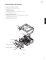
3. Removal of Sub-chassis Unit
a. Remove 2 screws (
⑧
). (Fig. 2)
b. Remove C
B5
0
5
, C
B5
0
8
, C
B
706 and C
B85
3. (Fig. 2)
c. Release 2 hooks and then remove the sub
-
chassis unit. (Fig. 2)
4. Removal of DIGITAL P.C.B.
a. Remove 3 screws (
9
). (Fig. 3)
b. Remove 3 screws (
j
). (Fig. 2)
c. Remove C
B
21, C
B
301, C
B
303 and C
B
304 and then remove the DI
G
IT
A
L P.C.
B
. (Fig. 2)
5. Removal of DIGITAL P.C.B.
a. Remove 7 screws (
k
). (Fig. 3)
b. Remove screw (
l
) and screw (
m
). (Fig. 2)
c. Remove C
B
2, C
B
101, C
B
10
5
and C
B
404 and then remove the FUNCTION (1)–(3) P.C.
B
. (Fig. 2)
Fig. 2
Fig. 3


