4
Chapter 2—Touring the AD824
AD824—Owner’s Manual
D
COM PC/RS422 port
This 9-pin D-sub connector is for connecting the AD824 to a device for remote control,
such as a Yamaha DME32 or personal computer. It’s also used to connect to the previ-
ous AD824 in a multiple-unit system.
E
WORD CLOCK OUT connector
This BNC connector transmits the wordclock signal.
F
WORD CLOCK 75
Ω
ON/OFF switch
This switch is used to terminate the wordclock signal received at the WORD CLOCK
IN. See “Wordclocks” on page 14 for more information.
G
WORD CLOCK IN connector
This BNC connector is used to connect an external wordclock source. See “Wordclocks”
on page 14 for more information.
H
INPUT (BAL) connectors
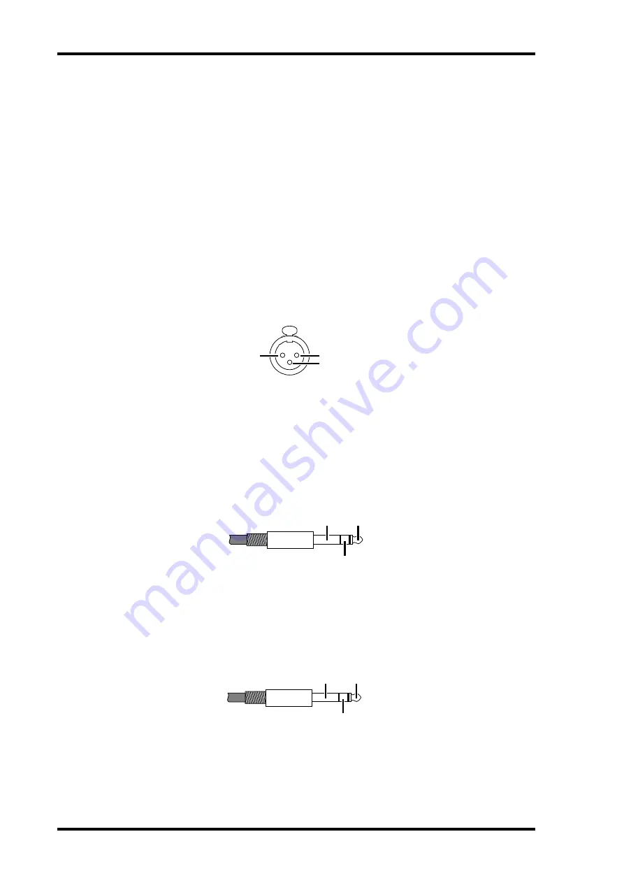
These female XLR-3-31-type connectors are the analog inputs. They’re electronically
balanced and are wired as follows: pin-1 ground, pin-2 hot (+), and pin-3 cold (–).
I
SLOT
This slot is for use with optional mini YGDAI cards, which offer various digital output
options. See “Digital I/O Cards” on page 7 for more information.
J
INSERT OUT (BAL) connectors
These balanced 1/4" TRS phone jacks are the insert outputs, or send connectors. The
insert point on each channel is located between the head amplifier and A/D converter.
They’re electronically balanced and are wired as follows: tip=hot, ring=cold, and
sleeve=ground.
K
INSERT IN (BAL) connectors
These balanced 1/4" TRS phone jacks are the insert inputs, or return connectors. The
insert point on each channel is located between the head amplifier and A/D converter.
The signal level indicators are located after the INSERT IN connector. They’re electron-
ically balanced and are wired as follows: tip=hot, ring=cold, and sleeve=ground.
ground
hot
cold
ground
hot
cold
ground
hot
cold


