[60]
[140]
[140]
[140]
DC
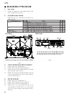
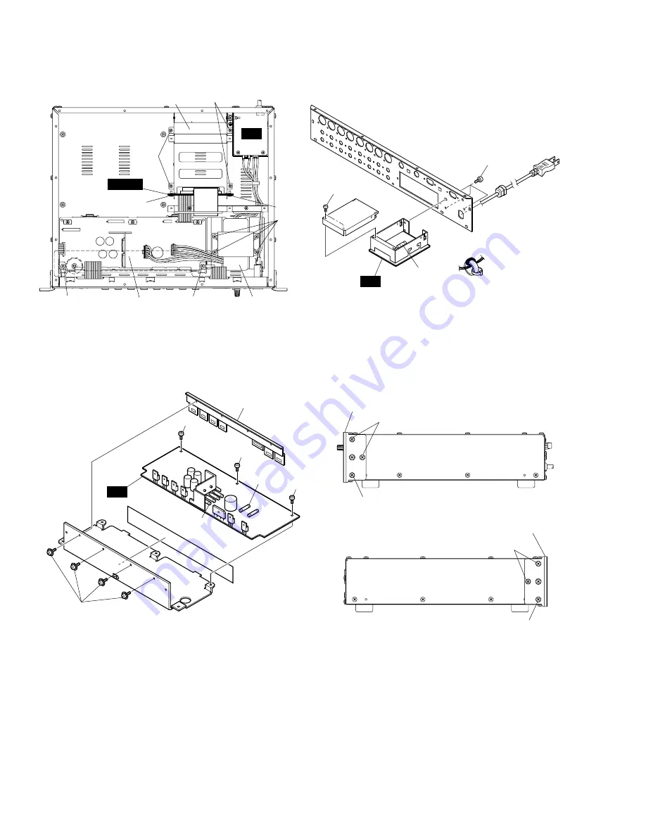
[40]: Bonding Tapping Screw-B 3.0X8 MFZN2BL (VN413300)
[60]: Pan Head Screw SP4.0X8 MFZN2Y (EL200020)
Fig. 7
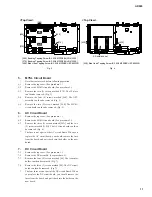
[140]: Oval Head Screw B4.0X10 MFZN2BL (V6221000)
Fig. 8
• DC Assembly
[40]
[40]
[40]
Transistor holder
Rack mount angle
Rack mount angle
<Right View>
<Left View>
[140]
Fuses
Fuses
AD824
12
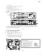
8.
PN Circuit Board and SW Circuit Board
8-1
Remove the top cover. (See procedure 1.)
8-2
Remove the six (6) screws marked [140]. The right and
left rack mount angles can then be removed. (Fig. 8)
8-3
Remove the knob marked [110B]. (Fig. 9)
8-4
Remove the six (6) screws marked [80]. The front panel
can then be removed. (Fig. 9)
AC
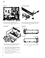
[250]: Bind Head Screw 4.0X8 MFZN2BL (EG340360)
[260]: Bonding Tapping Screw-B 3.0X8 MFZN2BL (VN413300)
Fig. 5
<Top View>
DC assembly
OPT assembly
MYSL
Power transformer
[190]
[260]
[260]
[210]
[250]
[250]
[210]
[110A] X2
Fuse
AC
[50A]: Bind Head Tapping Screw-B A4.0X8 MFZN2BL (VC688800)
[110A]: Bonding Tapping Screw-B 3.0X8 MFZN2BL (VN413300)
Fig. 6
• Rear Panel Assembly
[50A] X3
Summary of Contents for AD824
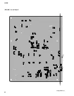
Page 22: ...MAIN Circuit Board B B 3NA V579130 AD824 22 ...
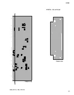
Page 23: ...E B B MAIN MYSL 3NA V579130 MYSL Circuit Board AD824 23 Pattern side Pattern side ...
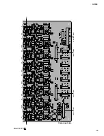
Page 24: ...3NA V579110 INPUT BAL 1 2 3 4 5 6 7 8 1 HA Circuit Board C C AD824 24 ...
Page 25: ...AD824 25 3NA V579110 to MAIN CN903 1 C C to JK CN202 to JK CN102 to DC CN007 Component side ...
Page 26: ...HA Circuit Board 3NA V579110 1 D D AD824 26 ...
Page 27: ...3NA V579110 1 D D AD824 27 Pattern side ...
Page 30: ...AD824 30 AD Circuit Board 3NA V579120 F F ...
Page 31: ...AD824 31 JK Circuit Board F F AD JK 3NA V579120 Pattern side Pattern side ...
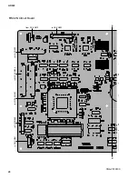
Page 33: ...PN Circuit Board 3NA V579100 1 H H H H AD824 33 Pattern side ...

