10
AD8HR
[70]: Bind Head Tapping Screw-S
3.0X6 MFZN2BL (EP630210)
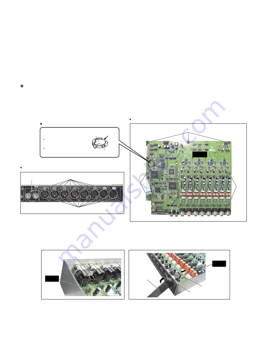
4.
MAIN シート
(所要時間: 約 7 分)
4-1.
トップカバーを外します。
(1 項参照)
4-2.
SUB シートを外します。
(2 項参照)
4-3.
COMB シートを外します。
(3 項参照)
4-4.
[50]のネジ 16 本、[60]のネジ 1 本、[70]のネジ 7 本、
[D]のネジ 2 本を外し、MAIN シートを外します。
(写真 1, 2, 3)
※
MAINシートを外す時は、INPUT端子のプッシュレ
バーを先に外すと、外しやすくなります。
1. ラッチ外し工具で A のように差し込みます。
(写真 4)
2. プッシュレバーを B のようにツマミ抜き取りレ
バーで外します。
(写真 4)
[70]
[70]
[70]
MAIN
Battery VN103500
VN103600(Battery holder for VN103500)
Notice for back-up battery removal
Push the battery as shown in figure,
then the battery will pop up.
Druk de batterij naar beneden zoals
aangeven in de tekening de batterij
springt dan naar voren.
Battery
Battery holder
Lithium Battery
(リチウム電池)
Photo. 3
Rear view
Photo. 2
Top view
[50]: Bind Head Tapping Screw-B
2.6X8 MFZN2BL (VB096700)
[60]: Bind Head Tapping Screw-B
3.0X8 MFZN2BL (EP600190)
5.
DC シート
(所要時間: 約 3 分)
5-1.
トップカバーを外します。
(1 項参照)
5-2.
[230]のネジ 4 本を外し、DC シートを外します。
(写真 5)
[50]
[60]
[50]
MAIN
MAIN
Tool (AAX52710)
Tool (AAX52710)
Tool (AAX000021)
(プッシュレバー)
Push lever
A
B
Photo. 4
(+バインドSタイト)
4.
MAIN Circuit board
(Time required: About 7 minute)
4-1.
Remove the top cover. (See Procedure 1.)
4-2.
Remove the SUB circuit board. (See Procedure 2.)
4-3.
Remove the COMB circuit board. (See Procedure 3.)
4-4.
Remove the sixteen (16) screws marked [50], the
screw marked [60], the seven (7) screws marked [70]
and the two (2) screws marked [D]. The MAIN circuit
board can then be removed. (Photo. 1, 2, 3)
First of all, remove the push lever of the INPUT
terminal for easy removal of the main circuit board.
1.
Insert with a latch-removing tool as shown in (A).
(Photo 4)
2.
Remove the push lever, using a knob extractor lever
as shown in (B). (Photo 4)
(写真3)
(写真2)
(+バインドBタイト)
(+バインドBタイト)
5.
DC Circuit board
(Time required: About 3 minute)
5-1.
Remove the top cover. (See Procedure 1.)
5-2.
Remove the four (4) screws marked [230]. The DC
circuit board can then be removed. (Photo. 5)
(写真4)


