AD8HR
11
6.
電源ユニット
(所要時間: 約 4 分)
6-1.
トップカバーを外します。
(1 項参照)
6-2.
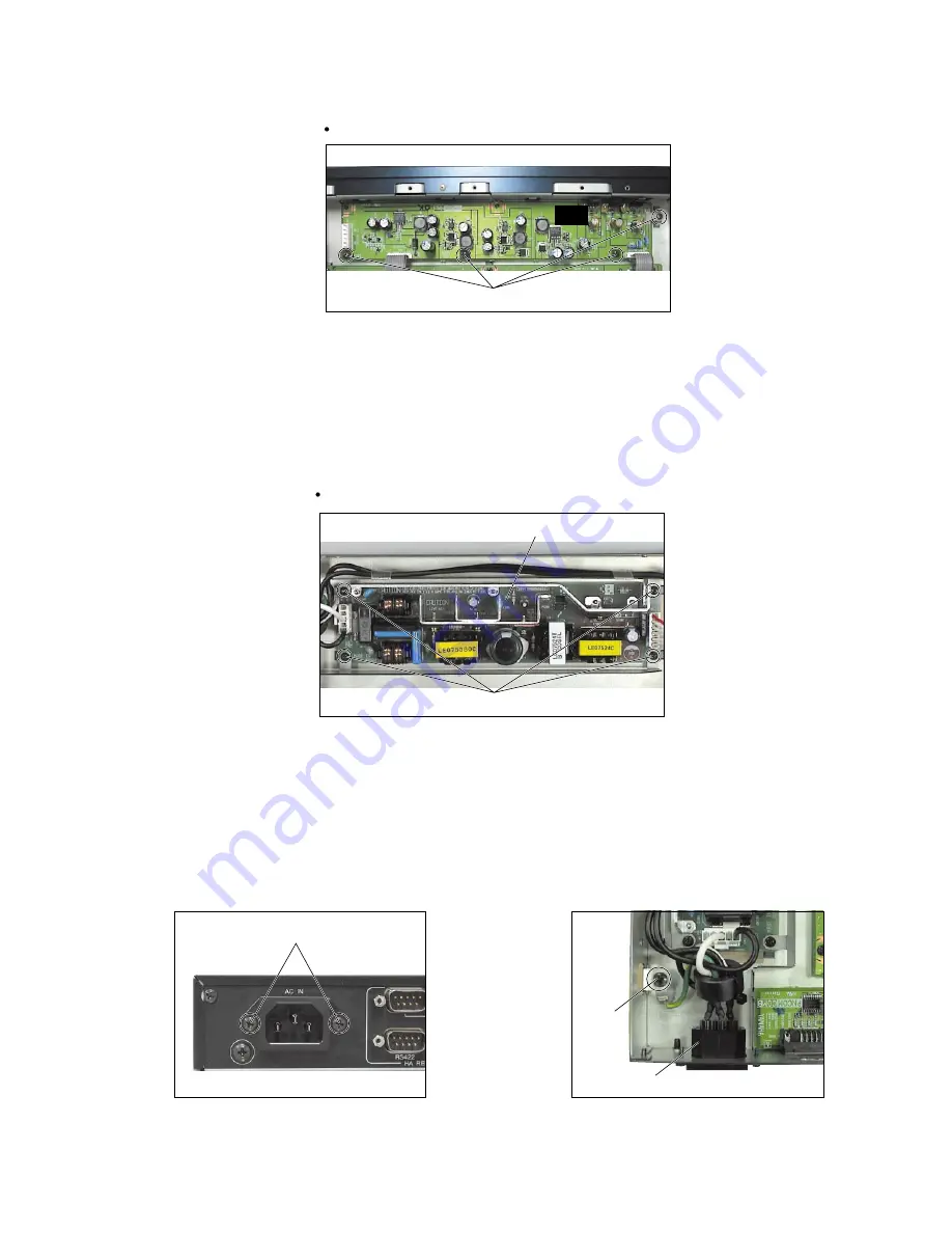
[130]のネジ 4 本を外し、電源ユニットを外します。
(写真 6)
7.
インレット Ass'y
(所要時間: 約 3 分)
7-1.
トップカバーを外します。
(1 項参照)
7-2.
[210]のネジ 2 本、
[220]のネジ 1 本を外し、インレッ
ト Ass'y を外します。
(写真 7, 8)
[210]
[220]
AC inlet assembly
(インレットAss'y)
[130]
Power supply unit
(電源ユニット)
[130]: Bind Head Tapping Screw-S
3.0X6 MFZN2BL (EP630210)
Photo. 6
Top view
[210]: Bind Head Tapping Screw-B
3.0X8 MFZN2BL (EP600190)
Photo. 7
[220]: Bind Head Screw
4.0X8 MFZN2BL (EG340360)
Photo. 8
[230]
DC
Photo. 5
Top view
[230]: Bind Head Tapping Screw-S
3.0X6 MFZN2BL (EP630210)
6.
Power supply unit
(Time required: About 4 minute)
6-1.
Remove the top cover. (See Procedure 1.)
6-2.
Remove the four (4) screws marked [130]. The power
supply unit can then be removed. (Photo. 6)
7.
AC inlet assembly
(Time required: About 3 minute)
7-1.
Remove the top cover. (See Procedure 1.)
7-2.
Remove the two (2) screws marked [210] and the
screw marked [220]. The AC inlet assembly can then
be removed. (Photo. 7, 8)
(+バインドSタイト)
(写真6)
(+バインドBタイト)
(写真7)
(+バインド小ネジ)
(写真8)
(写真5)
(+バインドSタイト)


