12
AD8HR
[300]
[300]
PN
9.
SW シート
(所要時間: 約 4 分)
9-1.
トップカバーを外します。
(1 項参照)
9-2.
フロントパネルを外します。
(8 項参照)
9-3.
ボタン PSW を外します。
(写真 12)
9-4.
[280]のネジ 2 本を外し、SW シートを外します。
(写真 12)
10.
PN シート
(所要時間: 約 4 分)
10-1.
トップカバーを外します。
(1 項参照)
10-2.
フロントパネルを外します。
(8 項参照)
10-3.
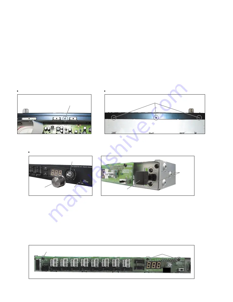
[300]のネジ 3 本を外し、PN シートを外します。
(写真 13)
[470]
[460]
Bottom view
Top view
[460]: Flat Head Screw-S
3.0X6 MFAN2Y (WB451000)
Photo. 9
[470]: Bind Head Tapping Screw-S
3.0X6 MFZN2BL (EP630210)
Photo. 10
Front view
Front panel
(フロントパネル)
Knob assembly
(ノブAss'y)
Hexagonal nut
[280]
(特殊六角ナット)
Button PSW
(ボタンPSW)
Photo. 13
[300]: Bind Head Tapping Screw-S
3.0X6 MFZN2BL (EP630210)
Photo. 11
[280]: Bind Head Tapping Screw-S
3.0X6 MFZN2BL (EP630210)
Photo. 12
8.
Front panel
(Time required: About 4 minute)
8-1.
Remove the top cover. (See Procedure 1.)
8-2.
Remove the screw marked [460], the three (3)
screws marked [470], the knob (GAIN control) and
the hexagonal nut of a front panel side. The front
panel can then be removed. (Photo. 9, 10, 11)
9.
SW Circuit board
(Time required: About 4 minute)
9-1.
Remove the top cover. (See Procedure 1.)
9-2.
Remove the front panel. (See Procedure 8.)
9-3.
Remove the button PSW. (Photo. 12)
9-4.
Remove the two (2) screws marked [280]. The SW
circuit board can then be removed. (Photo. 12)
10.
PN Circuit board
(Time required: About 4 minute)
10-1. Remove the top cover. (See Procedure 1.)
10-2. Remove the front panel. (See Procedure 8.)
10-3. Remove the three (3) screws marked [300]. The PN
circuit board can then be removed. (Photo. 13)
(Sタイト平頭)
(写真9)
(+バインドSタイト)
(写真10)
(写真13)
(+バインドSタイト)
(写真11)
(+バインドSタイト)
(写真12)
8.
フロントパネル
(所要時間: 約 4 分)
8-1.
トップカバーを外します。
(1 項参照)
8-2.
[460]のネジ 1 本、
[470]のネジ 3 本を外し、フロント
パネル面のツマミ(GAINコントロール)と特殊六角
ナット 1 個を外し、フロントパネルを外します。
(写真 9, 10, 11)


