AD8HR
39
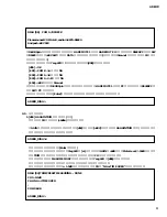
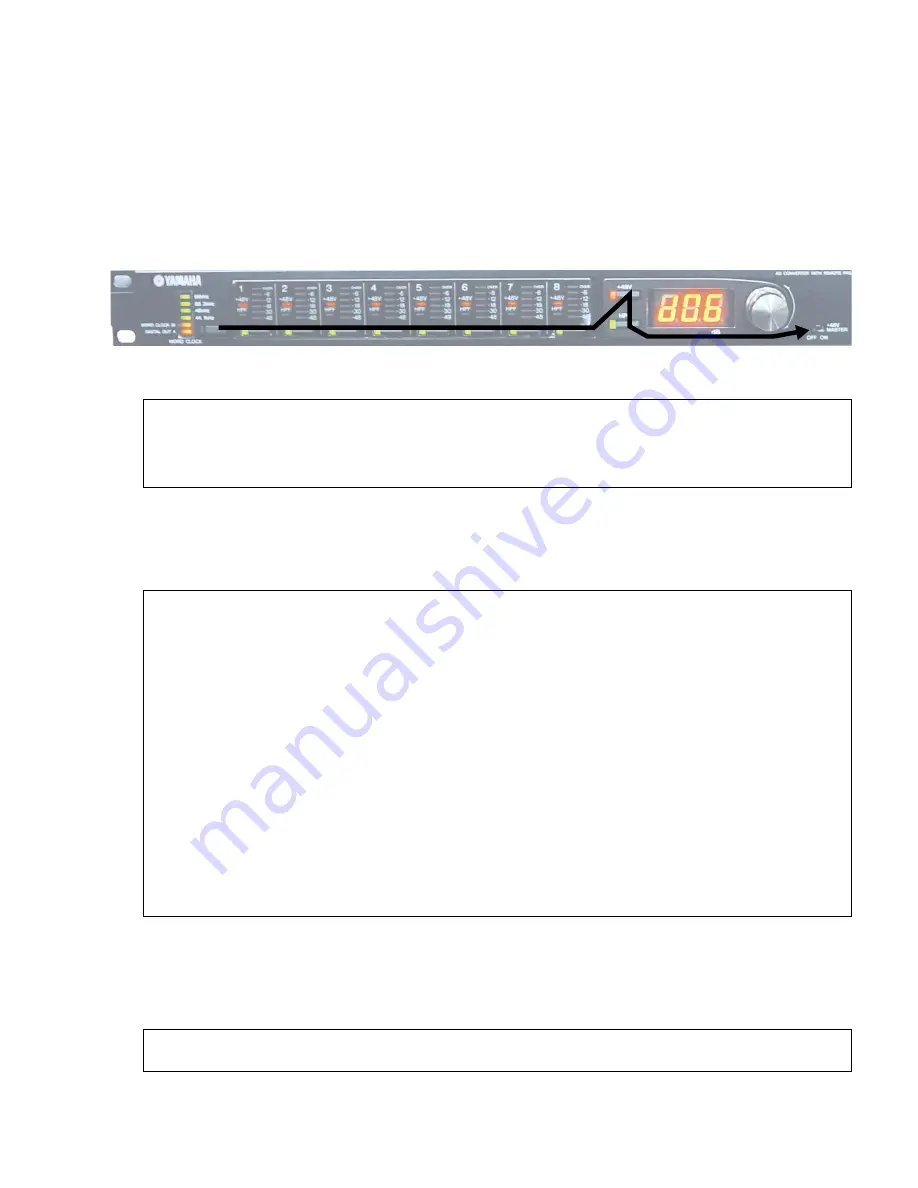
Executing a test program No. displays [----] on the 7segment LED, and a sequence runs to test the switch connection as
shown in the sequence in the figure below. Press the applicable switch to run the test. The sequence is as follows.
1. The LED of the applicable LED flashes. (If testing WORD CLOCK, then all WORD CLOCK LED flash.)
2. Press the switch and the switch changes from flashing to lit up.
3. The next test switches are shown with a flashing LED on the display. Press the applicable switch.
After pressing HPF, change a +48V MASTER switch to check the switch.
The terminal software shows the following message:
DIAG [02] SWITCH CHECK ........... DONE
AD8HR_DIAG>
4. If there is no error, then the 7 segment LED starts flashing with "06" in [d06], and the program prepares for the next test.
The above steps 1-3 are repeated and if a connection error or time-over occurs, the message [E02] flashes 3 times
on the 7 segment LED and then terminates with [d02] lighting up.
AD8HR_DIAG>6
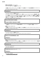
2-4. [d06] COM A/B Test (HA REMOTE 1/2 terminal test)
Select the test program No. [d06] on the GAIN encoder and press the [+48V] key to run this COM A and B test.
(Read COM A as HA REMOTE 1 terminal and COM B as HA REMOTE 2 terminal.)
You can also enter the following characters from the terminal software:
and run the test. (You don't need to press the Enter key.)
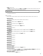
The terminal software display appears as follows.
AD8HR_DIAG>2
DIAG [02]
SWITCH CHECK
NG or TIME OVER
WORD CLOCK
(SW160)
SEL
1
(SW161)
SEL
2
(SW162)
SEL
3
(SW163)
SEL
4
(SW164)
SEL
5
(SW165)
SEL
6
(SW166)
SEL
7
(SW167)
SEL
8
(SW168)
+48V
(SW169)
HPF
(SW170)
+48V MASTER
(SW151)
AD8HR_DIAG>_
(Example of Time-over in case that the switch is not pushed at all.)


