AD8HR
57
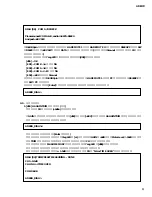
6. Measurement of double-channel mode Fs
Conditions: Use System Two.
Test DIGITAL OUT A on CH 1 & 2.
WORD CLOCK INT96kHz
q
Start up the system by setting the power switch to ON while holding down the WORD CLOCK key and Channel Select
Button [2] key. Now check that "AE2" appears on the 7 segment LED.
w
Check that the value on the Digital I/O panel INPUT screen of System Two is as shown below.
Sample Rate-ISR : 48kHz
±
0.1kHz
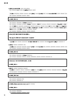
7. Factory settings
Initializing (Factory Preset)
Turning the power ON while holding down the Channel Select Button [4] key and [+48V] key to start up allows initializing
the system to the factory settings. (+48V MASTER SW: OFF)
Value is as follows.
WORD CLOCK
INT 48kHz
HA GAIN
10dB (All CH)
+48V
OFF (All CH)
HPF
OFF (All CH)
HPF FREQ
80Hz (All CH)
GAIN TRIM
Factory setting value (All CH)
LED luminance
7 (Max)
Others: switches not controlled by the CPU are as follows.
+48V MASTER: OFF
PC RS422: RS422
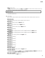
5-2. WORD CLOCK EXT
Conditions: Select the following for WORD CLOCK.
Select WORD CLOCK during testing of WORD CLOCK IN.
Select DIGITAL OUT A during testing of DIGITAL OUT A.
During WORD CLOCK IN testing, select the oscillator frequency from the values in the following table.
During DIGITAL OUT A testing, select the System Two frequency (Sample Rate) from the values in the following table.
q
Jitter (for both WORD CLOCK IN and DIGITAL OUT A)
WORD CLOCK
INT44.1kHz
INT48kHz
INT88.2kHz
INT96kHz
Tolerance Range
2nsec or less
2nsec or less
2nsec or less
2nsec or less
WORD CLOCK
44.1kHz
48kHz
88.2kHz
96kHz
Tolerance Range
5nsec or less
5nsec or less
5nsec or less
5nsec or less
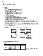
5-1. WORD CLOCK INT
Conditions: Select a WORD CLOCK value from the following table.
q
Jitter


