AD8HR
9
DISASSEMBLY PROCEDURE
1.
トップカバー
(所要時間: 約 3 分)
1-1.
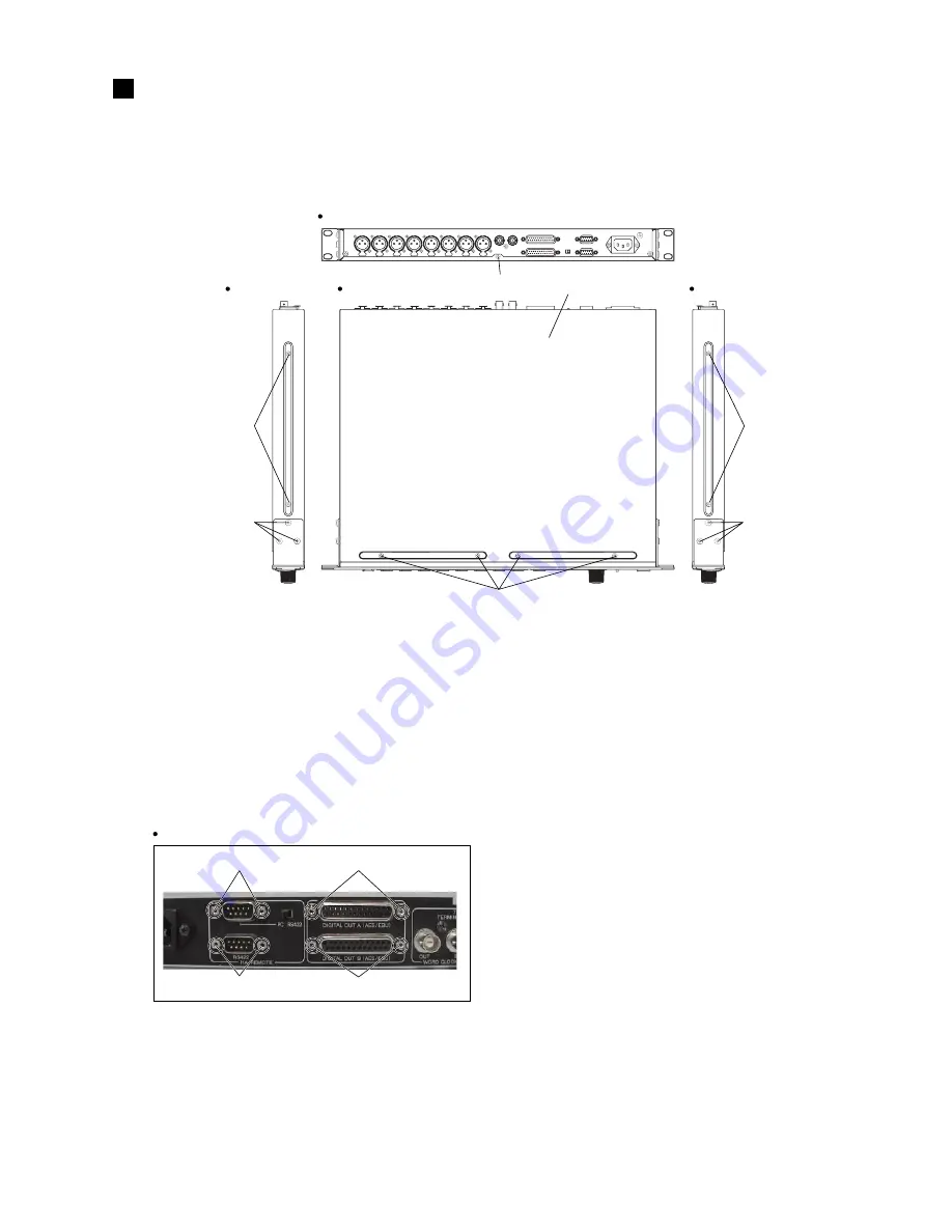
[500]のネジ 9 本と[530]のネジ 6 本を外し、トップ
カバーを外します。
(図 1)
2.
SUB シート
(所要時間: 約 4 分)
2-1.
トップカバーを外します。
(1 項参照)
2-2.
[A]のネジ 2 本と[B]のネジ 2 本を外し、SUB シート
を外します。
(写真 1)
[500]: Bind Head Tapping Screw-S
3.0X6 MFZN2BL (EP630210)
[530]: Bind Head Tapping Screw-S
4.0X8 MFZN2BL (VI693100)
Fig.1
Top cover
[500]
(トップカバー)
[500]
[530]
[530]
[500]
[500]
Top view
Rear view
Side view
Side view
3.
COMB シート
(所要時間: 約 4 分)
3-1.
トップカバーを外します。
(1 項参照)
3-2.
SUB シートを外します。
(2 項参照)
3-3.
[C]のネジ 2 本を外し、COMB シートを外します。
(写真 1)
[A]
[B]
[D]
[C]
Rear view
Photo. 1
[A], [D]: Hex Locking Screw
JFS-2.6S-BIWL (VS604900)
[B], [C]: Hex Locking Screw
(分解手順)
1.
Top cover
(Time required: About 3 minute)
1-1.
Remove the nine (9) screws marked [500] and the
six (6) screws marked [530]. The top cover can then
be removed. (Fig.1)
2.
SUB Circuit board
(Time required: About 4 minute)
2-1.
Remove the top cover. (See Procedure 1.)
2-2.
Remove the two (2) screws marked [A] and the two
(2) screws marked [B]. The SUB circuit board can
then be removed. (Photo. 1)
(+バインドSタイト)
(+バインドSタイト)
(図1)
3.
COMB Circuit board
(Time required: About 4 minute)
3-1.
Remove the top cover. (See Procedure 1.)
3-2.
Remove the SUB circuit board. (See Procedure 2.)
3-3.
Removr the two (2) screws marked [C]. The COMB
circuit board can then be removed. (Photo. 1)
(写真1)
(六角ロックネジ)
(六角ロックネジ)


