AV-S70/NX-SW70
AV-S70/NX-SW70
●
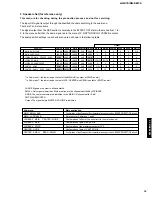
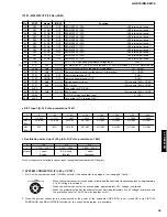
KEY input (A-C) Pull-up resistance 10k
Ω
Ω
V
KEY 0
(98pin)
KEY 1
(96pin)
0
— 0.556
VOLUME
N
DSP
+2k
— 1.111
VOLUME
B
INPUT
+10k
— 3.889
NO KEY
NO KEY
+2.4k
— 2.222
NO KEY
NO KEY
+3.9k
— 2.778
NO KEY
NO KEY
+5.6k
— 3.333
NO KEY
NO KEY
+1.8k
— 1.667
NO KEY
NO KEY
+24k
— 4.444
NO KEY
NO KEY
●
Destination select input (95 pin A-D) Pull-up resistance 10k
Ω
Ω
V
Destination
51k
3.889 — 4.444
J model
(Japanese)
16k
2.778 — 3.333
J model
(English)
27k
3.333 — 3.889
B, G models
(English)
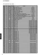
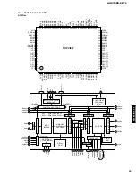
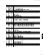
IC701 : M30218FCFP (16 bit
µ
-COM)
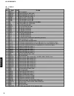
No.
PORT
Name
IN/OUT
Function
78
P52
FLD10
OUT
SEGMENT 25 (P25)
(VEE internal pull-down)
79
P51
FLD9
OUT
SEGMENT 26 (P26)
(VEE internal pull-down)
80
P50
FLD8
OUT
SEGMENT 27 (P27)
(VEE internal pull-down)
81
P67
FLD7
OUT
SEGMENT 28 (P28)
(VEE internal pull-down)
82
P66
FLD6
OUT
SEGMENT 29 (P29)
(VEE internal pull-down)
83
P65
FLD5
OUT
SEGMENT 30 (P30)
(VEE internal pull-down)
84
P64
FLD4
OUT
SEGMENT 31 (P31)
(VEE internal pull-down)
85
P63
FLD3
OUT
SEGMENT 32 (P32)
(VEE internal pull-down)
86
P62
FLD2
OUT
SEGMENT 32 (P33)
(VEE internal pull-down)
87
P61
FLD1
OUT
SEGMENT 34 (P34)
(VEE internal pull-down)
88
P60
FLD0
OUT
SEGMENT 35 (P35)
(VEE internal pull-down)
89
VEE
-
-
P0, P1, P5, P6 pull-down resistance voltage input
[-29V]
90
P107
AN7
A-D IN
SW protection IN
[4.0-5.0V:SW provided, 2.5V:SW not provided, 0-2.0V:SW protection ON]
91
P106
AN6
A-D IN
AUTO POWER ON/OFF identify IN (music signal)
[0 — VREF]
92
P105
AN5
A-D IN
Center unit power supply voltage detect IN (protection)
[0 — VREF]
93
P104
CMOS
OUT
Night mode switching OUT
[1:ON]
94
P103
CMOS
OUT
Center unit power supply OUT
[1:ON]
95
P102
AN2
A-D IN
Destination select input
[Pull-up with 10k
Ω
> VREF]
96
P101
AN1
A-D IN
KEY 1 input
[Pull-up with 10k
Ω
> VREF]
97
AVSS
-
-
Connected to VSS (GND)
98
P100
AN0
A-D IN
KEY O input
[Pull-up with 10k
Ω
> VREF]
99
VREF
-
-
A-D, D-A reference voltage input
[— VCC]
100
AVCC
-
-
Connected to VCC terminal (+5V)
16
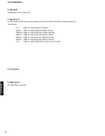
For any voltage that is not within the above range, the applicable destination is EX (English).
✽
✽
SYSTEM CONNECTOR (Pin 90 of IC701)
1. Pin 3 of the system connector (CN602) detects if the subwoofer is equipped / not equipped / faulty.
• When the system connector is connected correctly and the subwoofer is operating properly, approximately
4 to 5V voltage is obtained.
• When the system connector is not connected, approximately 2.5V voltage is obtained.
• When the protection circuit of the subwoofer is at work, approximately 0 to 2V voltage is obtained and
the protection circuit of AV-S70 works together with it.
2. When the system connector is not connected or the power of the subwoofer (NX-SW70) is not turned ON, only VIRTUAL
SURROUND and MONO MOVIE functions of the sound field program are available.
2
4
1
8
6
5
3
7
CN602
SYSTEM CONNECTOR

