–13–
EBA00028
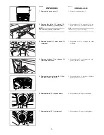
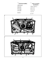
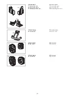
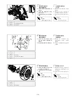
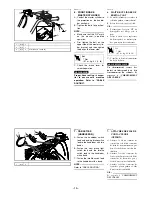
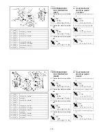
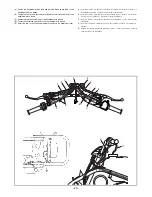
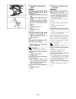
1. FRONT SHOCK
ABSORBERS
A: Install the shock absorbers as
shown.
B: Install the flange bolts from
rear to front.
C: Tighten the nuts to specifica-
tion.
T
R
.
.
Nut
45 Nm
(4.5 m · kg, 32 ft · lb)
EBA00031
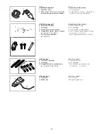
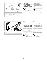
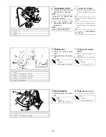
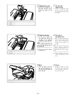
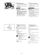
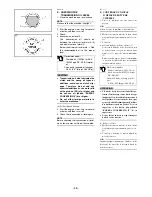
2. REAR SHOCK
ABSORBER
A: Install the thrust covers onto
the rear shock absorber as
shown.
B: Bend the end of the cotter pin.
EBA00033
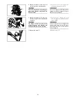
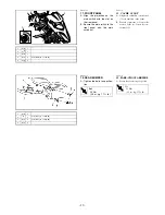
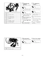
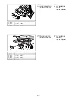
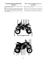
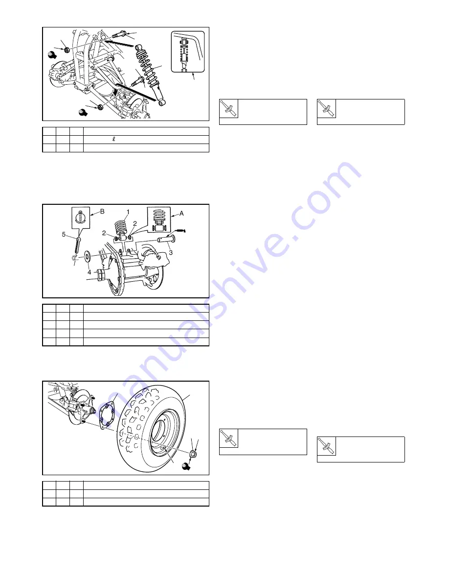
3. FRONT WHEELS
A: Install the wheels so that the
air valves are facing out.
B: Tighten the nuts to specifica-
tion.
T
R
.
.
Nut
45 Nm
(4.5 m · kg, 32 ft · lb)
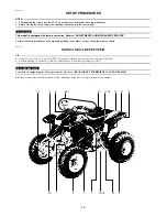
FBA00028
1. AMORTISSEURS
AVANT
A: Monter les amortisseurs comme
illustré.
B: Monter les vis à collerette en
montant d’abord les vis arrière.
C: Serrer les écrous au couple spéci-
fié.
T
R
.
.
Écrou
45 Nm
(4,5 m · kg, 32 ft · lb)
FBA00031
2. AMORTISSEUR
ARRIÈRE
A: Monter les cache-butées sur
l’amortisseur arrière comme
illustré.
B: Replier l’extrémité de la goupille
fendue.
FBA00033
3. ROUES AVANT
A: Monter les roues de sorte que les
valves d’air soient dirigées vers
l’extérieur.
B: Serrer les écrous au couple spéci-
fié.
T
R
.
.
Écrou
45 Nm
(4,5 m · kg, 32 ft · lb)
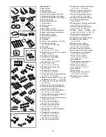
1
(3)-C
2
2
(3)-V
4
d = 10 (0.39), = 48 (1.89)
3
(5)-V
4
d = 10 (0.39)
3
3
2
1
2
B
A
B
C
C
45
45
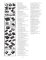
1
1
2
(5)-V
2
3
(2)-V
1
d = 12 (0.47)
4
(5)-V
1
d = 12 (0.47), D = 20 (0.79)
5
(5)-V
1
*
1
(5)-C
2
2
S
2
3
(5)-V
8
d = 10 (0.39)
1
2
3
A
45
B


