–14–
EBA00034
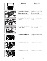
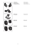
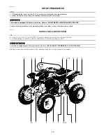
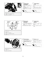
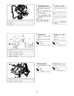
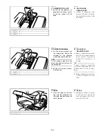
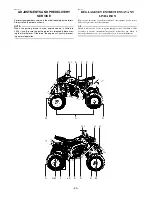
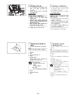
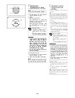
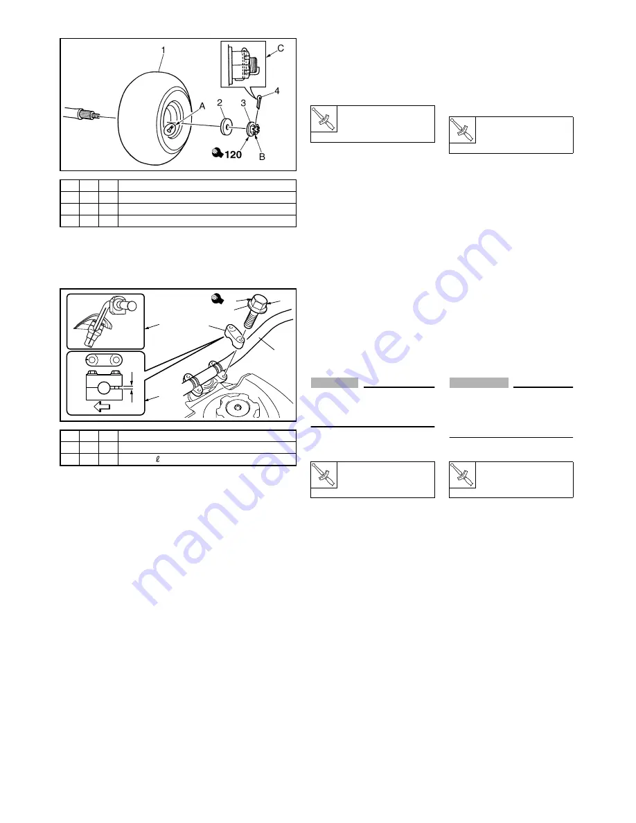
4. REAR WHEELS
A: Install the wheels so that the
air valves are facing out.
B: Tighten the nuts to specifica-
tion.
C: Bend the ends of the cotter
pins.
T
R
.
.
Nut
120 Nm
(12.0 m · kg, 85 ft · lb)
EBA00013
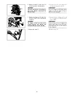
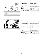
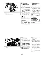
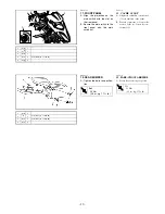
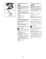
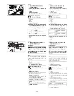
5. HANDLEBAR
A: Move the handlebar up until it
is aligned with the steering
shaft.
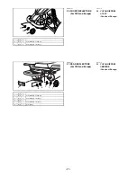
B: Install each handlebar holder
with its punch mark facing for-
ward.
CAUTION:
_
First tighten the bolts on the
front side, and then tighten the
bolts on the rear side.
C: Tighten the bolts to specifica-
tion.
T
R
.
.
Bolt
23 Nm
(2.3 m · kg, 17 ft · lb)
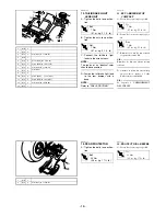
FBA00034
4. ROUES ARRIÈRE
A: Monter les roues de sorte que les
valves d’air soient dirigées vers
soi.
B: Serrer les écrous au couple spéci-
fié.
C: Replier l’extrémité des goupilles
fendues.
T
R
.
.
Écrou
120 Nm
(12,0 m · kg, 85 ft · lb)
FBA00013
5. GUIDON
A: Relever le guidon jusqu’à ce qu’il
soit aligné sur la colonne de
direction.
B: Monter les demi-paliers de gui-
don en dirigeant leur repère poin-
çonné vers l’avant.
ATTENTION:
_
Serrer d’abord les vis situées à
l’avant des demi-paliers de guidon,
puis serrer les vis situées à
l’arrière.
C: Serrer les vis au couple spécifié.
T
R
.
.
Vis
23 Nm
(2,3 m · kg, 17 ft · lb)
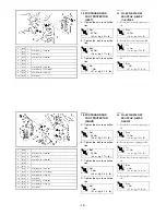
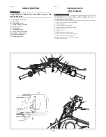
1
S
2
2
(5)-V
2
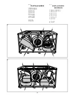
d = 14 (0.55), D = 33 (1.30)
3
(5)-V
2
d = 14 (0.55)
4
(5)-V
2
1
1
2
2
3
4
d = 8 (0.31), = 35 (1.38)
FWD
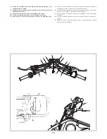
1
2
3
23
B
C
A
*
*
*


