7
SPEAKER SYSTEMS
BR10/BR12/BR15/BR12M/BR15M
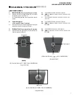
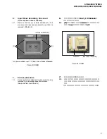
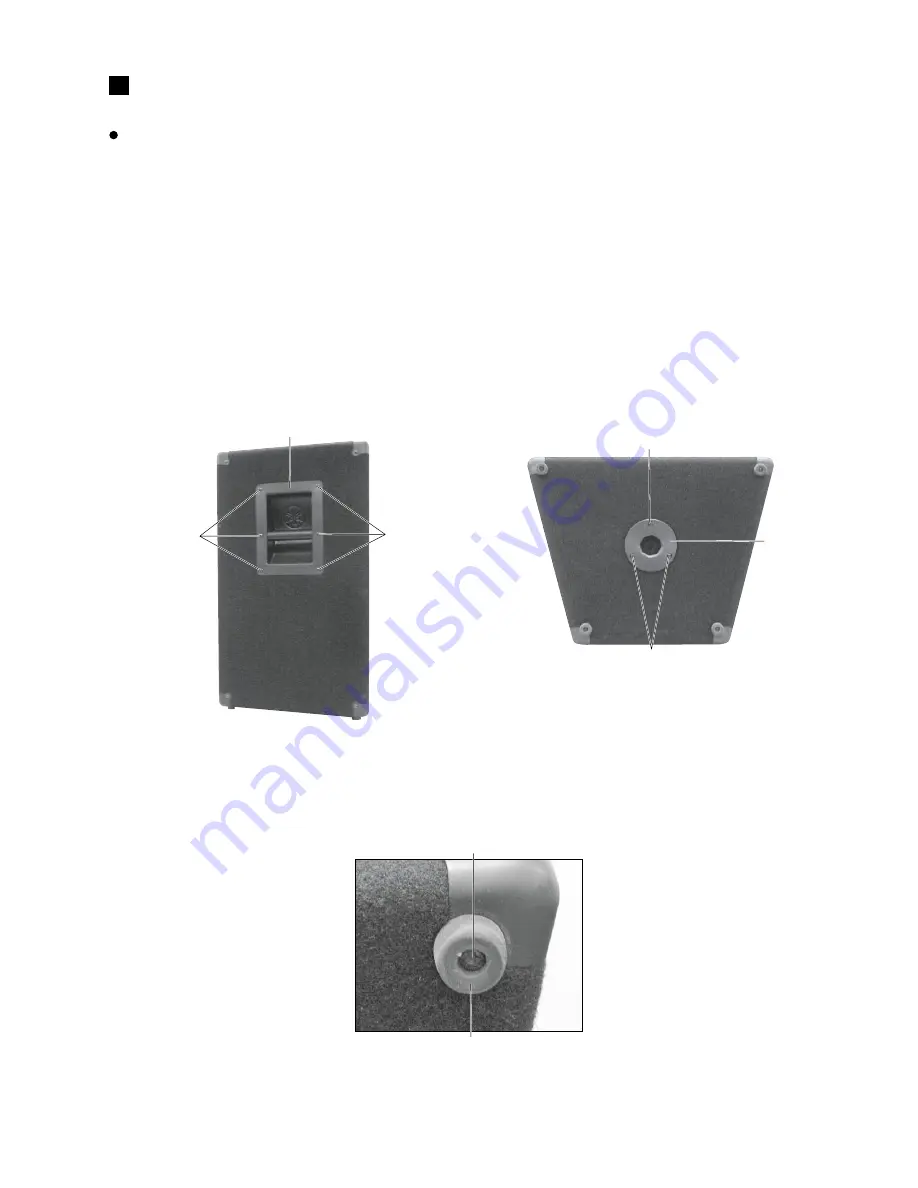
Photo.1
(写真1)
[27]: Truss Head SM Screw
#8 x 3/4 BLK (ETAI1230)
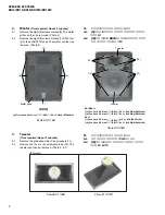
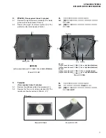
Photo.3
(写真3)
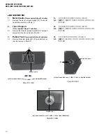
Photo.2
(写真2)
[37]: Pan Head PB Screw
#10 x 1 BLK (EKY01240)
[41]: Pan Head PB Screw
#10 x 1 BLK (EKY01240)
(BR15)
[27]
[27]
Metal handle
[37]
[37]
Tripod support
[41]
Rubber foot
DISASSEMBLY PROCEDURE
BR10/BR12/BR15
(分解手順)
1.
Metal Handle
(Time required: About 1 minute)
1-1
Remove the six (6) screws marked [27]. The metal
handle then removed. (Photo. 1)
*
For the installing position, see the parts list of each
model.
2.
Tripod Support
(Time required: About 1 minutes)
2-1
Remove the three (3) screws marked [37]. The tripod
support can then be removed. (Photo.2)
3.
Rubber Foot
(Time required: About 1 minutes)
3-1
Remove the screw marked [41]. The rubber foot can
then be removed. (Photo.3)
1.
メタルハンドル
(所要時間:約 1 分)
1-1
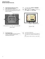
[27]のネジ6本を外し、メタルハンドルを外します。
(写真 1)
※
取付位置は、
各モデルのパーツリストを参照してく
ださい。
2.
スタンド受け台
(所要時間:約 1 分)
2-1
[37]のネジ3本を外し、スタンド受け台を外します。
(写真 2)
3.
ラバーフット
(所要時間:約 1 分)
3-1
[41]のネジ 1 本を外し、ラバーフットを外します。
(写真 3)
(ナベPBネジ)
(ナベPBネジ)
(トラスSMネジ)

