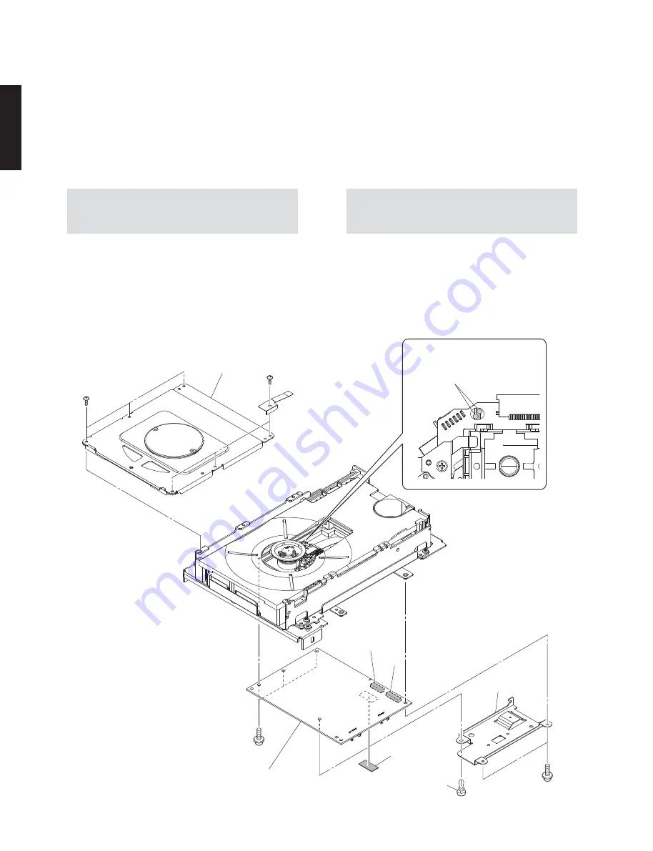
Pattern side to short-circuit with a solder
はんだでショートするパターン面
Solder
はんだ
CN211
CN210
Module board
モジュールボード
㉗
㉗
Clamp assembly
クランプ Ass'y
Radiation sheet
放熱シート
Radiation plate
放熱プレート
Push rivet
プッシュリベット
㉖
㉖
●
Disassembly of Loader Mechanism Unit
1. Removal of Module Board
a. Remove 6 screws (
㉖
) and then remove the clamp
assembly. (Fig. 11)
b. Solder the lands in the P.C.B. of the loader
mechanism unit with the anti-static soldering iron.
(Fig. 11)
● ローダーメカユニットの分解手順
1. モジュールボードの外し方
a. ㉖ のネジ 6 本を外し、クランプ Ass'y を外します。
(Fig. 11)
b. ローダーメカユニットの P.C.B. 上の端子間を静電
気対策はんだこてを使用してショートします。
(Fig. 11)
Fig. 11
注意:
修理終了時は、静電気対策はんだこてを使
用してショート箇所からはんだを除去しま
す。
Note:
After you have finished repairing, remove
the solder from the short-circuit location
with the antistatic soldering iron.
c. CN210、CN211 を外します。(Fig. 11)
d. ㉗ のネジ 5 本を外します。(Fig. 11)
e. モジュールボードを外します。(Fig. 11)
f. プッシュリベットを外します。(Fig. 11)
g. 放熱プレート、放熱シートを外します。(Fig. 11)
c. Remove CN210 and CN211. (Fig. 11)
d. Remove 5 screws (
㉗
). (Fig. 11)
e. Remove the module board. (Fig. 11)
f. Remove push rivet. (Fig. 11)
g. Remove the radiation plate and radiation sheet.
(Fig. 11)
22
CD-S2100
CD-S21
0
0
Summary of Contents for CD-S2100
Page 6: ... FRONT PANELS U K A B G L V S J models T model 6 CD S2100 CD S2100 ...
Page 7: ... REAR PANELS U V S models U model V model Bottom view 7 CD S2100 CD S2100 ...
Page 8: ...A B G L models K model T model 8 CD S2100 CD S2100 ...
Page 9: ...J model 9 CD S2100 CD S2100 ...
Page 84: ...MEMO MEMO CD S2100 84 ...
Page 85: ...MEMO 85 CD S2100 CD S2100 ...
Page 86: ...CD S2100 ...


