CDC-585/CDC-506/CDC-685/CDC-906
CDC-585/CDC-506
CDC-685/CDC-906
7
■
DISASSEMBLY PROCEDURES
(Remove parts in the order as numbered.)
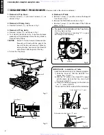
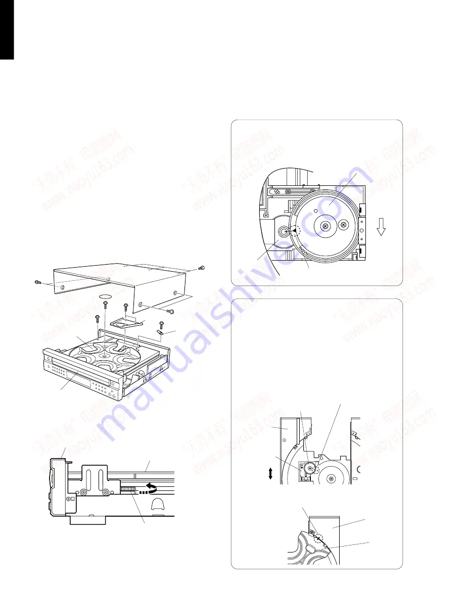
4. Removal of Table
a. Remove 1 screw (
t
) and then remove the Support/
T as shown in Fig. 1.
b. Remove the Plate/Table as shown in Fig. 1.
c. Remove 1 screw (
y
) and then take off the Table as
shown in Fig. 1.
Fig. 2
1. Removal of Top Cover
a. Remove 4 screws (
q
) and also 3 screws (
w
) as
shown in Fig. 1.
2. Removal of Clamp Ass’y
a. Remove 2 screws (
e
) as shown in Fig. 1.
3. Removal of Tray Ass'y
a. Remove 1 screw (
r
) as shown in Fig. 1.
b. Turn Gear/L0 as shown in Fig. 2 counter clockwise
gradually until immediately before the tray starts to
move and stop it there.
CAUTION : Gear/L0, if turned counter clockwise con-
tinuously, will mesh with the gear of the
tray and the tray will come out. When re-
moving the tray, use care so that Gear/L0
will not mesh with the gear of the tray.
c. Pull out the Tray Ass'y.
Fig. A
IMPORTANCE : Installation of Table.
Install the table according to the following procedure.
1) Slide the Lever so that the Gear/RT1 be-
comes free. (Fig.B-1)
2) With the “
▲
” mark on the Gear/RT1 aligned
with the same mark on the Tray, lock it with
the Lever. (Fig.B-1)
3) Install the Table by aligning it to the thick line
on “
/
” mark. (Fig.B-2)
*Check that the Table is locked after installation.
Fig. B-2
●
Precaution for installation of the Tray Ass'y.
On Tray Ass'y setting.
Check the Direction of marking “
▲
” on gear
according to this drawing.
Fig. 1
Gear/L0
Front Panel
Gear/L01
Lever
Tray
Gear/RT1
Fit the Gear/RT1 to “
▲
” mark.
Fig. B-1
Tray
Table
Marking
Fit the table to the thick line on “
/
” mark.
q
q
w
Table
y
Tray
Gear/L0
r
t
e
Top Cover
Plate/Table
Clamp Ass'y
Support/T
Lock
Unlock
www. xiaoyu163. com
QQ 376315150
9
9
2
8
9
4
2
9
8
TEL 13942296513
9
9
2
8
9
4
2
9
8
0
5
1
5
1
3
6
7
3
Q
Q
TEL 13942296513 QQ 376315150 892498299
TEL 13942296513 QQ 376315150 892498299


