CDR-HD1500
18
CDR-HD1500
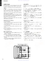
OPTICAL
OUTPUT
COAXIAL
OUTPUT
OPTICAL
INPUT
COAXIAL
INPUT
ANALOG
OUTPUT
ANALOG
INPUT
CB200
PJ200
CB201
PJ201
PJ202
PJ202
MAIN
PCB
DIR5
ACDR2
A/D
D/A
LPF
SW
DIT
selector
LPF
AUDIO patch
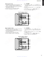
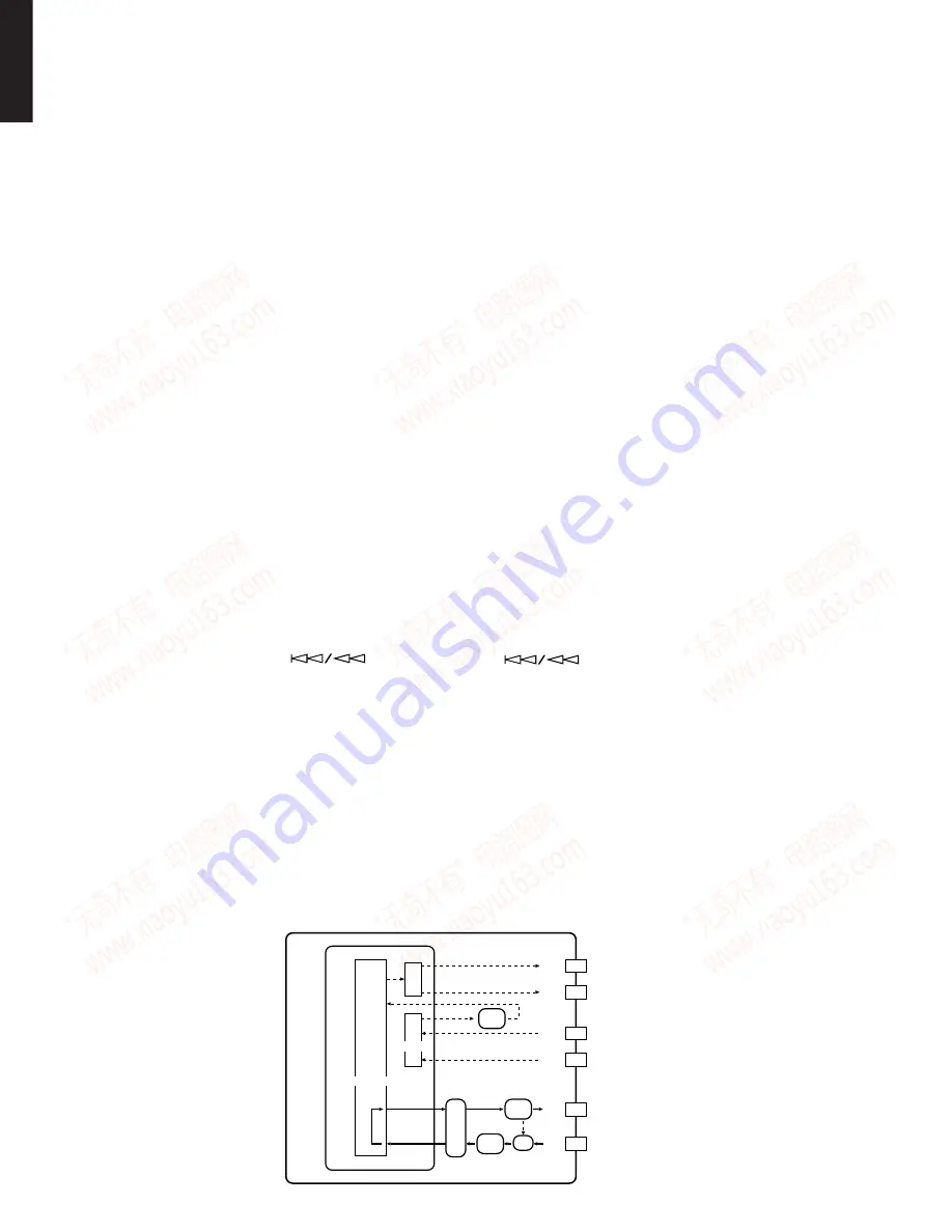
Signal flow diagram of Mode 1
モード1の信号フロー図
ACDR2不良
P.C.B.テストモードのモード1、モード2およびモード3を
使用することにより、ACDR2の動作を確認することがで
きます。
モード1では、アナログ信号の入・出力動作を確認します。
モード1ではCODECのA/DおよびD/Aコンバーター機能、
ACDR2内の信号の流れ、入・出力回路のローパスフィル
ターの動作を確認することができます。
モード2では、光デジタル信号の入力とデジタル出力動作
を確認します。
ACDR2はサブコードを復号し、トラックNo.とトラック時
間を表示します。この復号機能をテストするためにCDプ
レイヤーのデジタル出力を使用します。
モード3では、デジタル同軸信号入力とアナログ出力動作
を確認します。
P.C.B.テストモードの起動
1)電源を切ります。
2)次の3)の作業のためにHDDユニットを外します。(14
ページ)
3)C B 5 の1 ピンと2 ピン間をショートします。(M A I N
P.C.B. 41ページのE3)
4)J909とJ913間をショートします。
(OSD P.C.B. 44ペー
ジのC4)
5)電源を入れます。
6)P.C.B.テストモードが起動し、「TEST mode PCB」が表
示されます。
モード1動作確認
1)
キーを押し、モード1 に設定します。
「test mode 1」が表示されます。
2)ANALOG LINE INからアナログ信号を入力します。
入力信号:サイン波、1kHz、150mV (-14.2dBm)
3)ANALOG REC LEVELボリュームはMAXに設定しま
す。
4)ANALOG LINE OUTに出力されるアナログ信号を確認
します。
出力レベル:775mV(0dBm)
ACDR2 Check
By using the mode 1, mode 2 and mode 3 of the P.C.B.
test mode, the operation of the ACDR2 can be checked.
In Mode 1, the analog signal input/output operation is
checked.
In Mode 1, it is possible to check the A/D and D/A
converter function of CODEC, signal flow in ACDR2,
operation of the low pass filter in the input/output circuit.
In Mode 2, input of the optical digital signal and digital
output operation are checked.
The ADCR2 decodes the sub-code and displays the track
No. and the track time. To test this decoding function, the
digital output of the CD player is used.
In Mode 3, the digital coaxial signal input and analog
output operation are checked.
Starting the P.C.B. Test Mode
1) Turn off the power.
2) Remove the HDD unit for the convenience of the work
of the next step 3). (p. 14)
3) Short between pins No.1 and No.2 of the CB5. (MAIN
P.C.B., E3 in p.41)
4) Short between J909 and J913. (OSD P.C.B., C4 in
p.44)
5) Turn on the power.
6) The P.C.B. test mode is activated and “TEST mode
PCB” is displayed.
Mode 1 Operation Check
1) Set to Mode 1 by pressing the “
” key. “test
mode 1” is displayed.
2) Enter the analog signal through ANALOG LINE IN.
Input signal: Sine wave, 1kHz, 150mV (-14.2dBm)
3) Set the ANALOG REC LEVEL volume to the MAX
position.
4) Check the analog signal output at ANALOG LINE OUT.
www. xiaoyu163. com
QQ 376315150
9
9
2
8
9
4
2
9
8
TEL 13942296513
9
9
2
8
9
4
2
9
8
0
5
1
5
1
3
6
7
3
Q
Q
TEL 13942296513 QQ 376315150 892498299
TEL 13942296513 QQ 376315150 892498299


