background image

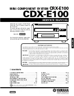
CDX-E100

CDX-E100

1 0 0 6 8 5

SERVICE MANUAL

CDX-E100

IMPORTANT NOTICE

This manual has been provided for the use of authorized YAMAHA Retailers and their service personnel.
It has been assumed that basic service procedures inherant to the industry, and more specifically YAMAHA Products, are already
known and understood by the users, and have therefore not been restated.

WARNING:

Failure to follow appropriate service and safety procedures when servicing this product  may result in personal
injury, destruction of expensive components and failure of the  product to perform as specified. For these reasons,
we advise all YAMAHA product owners that all service required should be performed by an authorized
YAMAHA Retailer or the appointed service representative.

IMPORTANT:

The presentation or sale of this manual to any individual or firm does not constitute authorization,  certification  or
recognition  of  any  applicable  technical  capabilities,  or establish a principle-agent relationship of any form.

The data provided is believed to be accurate and applicable to the unit(s) indicated on the cover.  The research, engineering, and
service departments of YAMAHA are continually striving  to improve YAMAHA products. Modifications are, therefore, inevitable
and specifications are subject to change without notice or obligation to retrofit. Should any discrepancy appear to exist, please contact
the distributor's Service Division.

WARNING:

Static discharges can destroy expensive components. Discharge any static electricity your body may have accumu-
lated by grounding yourself to the ground buss in the unit (heavy gauge black wires connect to this buss).

IMPORTANT:

Turn the unit OFF during disassembly and parts replacement. Recheck all work before you apply power to the unit.

IC DATA ................................................................ 12~16
DISPLAY DATA 
.......................................................... 17
IC BLOCK 
............................................................. 18~19
PIN CONNECTION DIAGRAM 
................................... 19
BLOCK DIAGRAM 
................................................ 20~21
PRINTED CIRCUIT BOARD 
................................ 22~27
SCHEMATIC DIAGRAM 
............................................. 28
PARTS LIST 
.......................................................... 29~37

■ 

CONTENTS

TO SERVICE PERSONNEL ..................................... 1~2
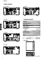
REAR PANELS 
............................................................. 3
SPECIFICATIONS 
......................................................... 3
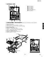
INTERNAL VIEW 
.......................................................... 4
DISASSEMBLY PROCEDURES 
.............................. 4~5
STANDARD OPERATION CHART 
.......................... 6~7
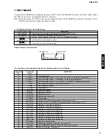
TEST MODE 
.............................................................. 8~9
ERROR MESSAGE 
............................................... 10~11

CRX-E100 is composed of RX-E100 and
CDX-E100. This is a service manual for
the CDX-E100.
For service manuals of RX-E100, please
refer to the service manuals with the
following publication numbers :

RX-E100

100684

For the system operation, please refer
to Service Manual for the RX-E100.

MINI COMPONENT SYSTEM 

CRX-E100

Summary of Contents for CDX-E100

Page 1: ...earch engineering and service departments of YAMAHA are continually striving to improve YAMAHA products Modifications are therefore inevitable and specifications are subject to change without notice or obligation to retrofit Should any discrepancy appear to exist please contact the distributor s Service Division WARNING Static discharges can destroy expensive components Discharge any static electr...

Page 2: ...cal electronic and or plastic where applicable components may also contain traces of chemicals found by the California Health and Welfare Agency and possibly other entities to cause cancer and or birth defects or other reproductive harm DO NOT PLACE SOLDER ELECTRICAL ELECTRONIC OR PLASTIC COMPONENTS IN YOUR MOUTH FOR ANY REASON WHATSOEVER Avoid prolonged unprotected contact between solder and your...

Page 3: ... VARNINGSMÄRKNING SE FIGUR FÖR STRÅLNING INGREPP I APPARATEN BÖR ENDAST FÖRETAGAS AV FACKMAN MED KÅNNEDOM OM LASER APPARATEN INNEHÄLLER EN LASERKOMPONENT SOM AVGER STRÅLNING ÖVERSTIGANDE GRÄNSEN FÖR LASERKLASS 1 VARNING OSYNLIG LASERSTRÅLNING NÄR DENNA DEL ÄR ÖPPNAD BETRAKTA EJ STRÅLEN Danish DETTE MÆRKAT ER ANBRAGT SOM VIST I ILLUSTRATIONEN FOR AT ADVARE BRUGEREN OM AT AP PARATET INDEHOLDER EN LA...

Page 4: ... Requirements U C models 120V AC 60Hz B G models 230V AC 50Hz A model 240V AC 50Hz R model 110 120 220 240V AC 50 60Hz Power Consumption 13W Dimensions W x H x D 217 x 108 x 290mm 8 9 16 x 4 1 4 x 11 7 16 Weight 3 0kg 6 lbs 9 oz Specifications are subject to change without notice U U S A model C Canadian model A Australian model B British model G European model R General model 240V G model 217 8 9...

Page 5: ... 4 screws w in Fig 1 b Lift the Top Cover at the rear and move it rear ward slantingly 2 Removal of Front Panel a Remove a connector CB6 in Fig 2 b Remove 2 e screws and 2 screws r in Fig 1 c Remove 2 hooks and then pull the Front Panel forward 3 Removal of CD Mechanism Unit a Remove 3 connectors CB1 CB2 CB3 in Fig 2 b Remove 4 screws t in Fig 1 Fig 2 Fig 1 e e q q w r Top Cover CD Mechanism Unit ...

Page 6: ...ws u in Fig 4 b Remove a pick up cable in Fig 4 c Remove 4 screws i and then remove the Drive Unit in Fig 4 d Remove the gear A in Fig 5 e Pull out the Sled Shaft in Fig 5 f Remove the Pick up Head 4 Removal of Tray Unit a Remove 2 screws y and then remove the Chuck ing Unit in Fig 3 b Remove 1 hook and then remove the Stopper Pin in Fig 3 c Rotate the Drive Gear and then open the Tray Unit in Fig...

Page 7: ...us gain rough ADJ Focus search operation Focus lock servo ON Spindle motor accelerated Tracking servo ON Spindle servo ON Feed servo ON Ò OPEN Ó appears in the indicator ÒTRVÓ signal is output until detection of LIMIT switch Stop after detection of LOADING switch Proceeds to next step after detection of LOADING switch if FLSW L IC5 21 pin Proceeds To Next Step LSON ÒHÓ IC3 3 pin FLOCK ÒHÓ ÒLÓ IC4 ...

Page 8: ...ector 0 00 appears in the time indicator Tracking balance ADJ only tray OPEN CLOSE Focus balance ADJ Focus gain ADJ Tracking gain ADJ TOC READ TRACK NO 1 is searched Set to SEARCH by means of Y T key After searching the beginning MUTE is cancelled PLAY Press the STOP key Laser OFF Forced feed return STOP MUTE OFF L H MUTE OFF H L 0 00 appears in the time indicator LSON H L IC3 3 pin ...

Page 9: ...Tray open close Auto adjustment mode 1 TR off set FO off set FO rough gain adjustment Auto adjustment mode 2 TR balance TR rough gain adjustment Auto adjustment mode 3 FO fine gain TR fine gain FO balance adjustment Move traverse reverse till the inner SW turn on Move traverse forward Stop traverse Accelerate spindle Decelerate spindle Spindle servo on Spindle free servo off Stop spindle FOON TROF...

Page 10: ... FO off set FO rough gain adjustment Auto adjustment mode 2 TR balance TR rough gain adjustment Auto adjustment mode 3 FO fine gain TR fine gain FO balance adjustment Reverse 1 track kick continuously Coefficient set up mode address down Forward 1 track kick continuously Coefficient set up mode address up Reverse 30 tracks kick continuously Coefficient set up mode upper digit down Forward 30 track...

Page 11: ... MN35511 does not give response of SENSE with resetting by the unit s microcomputer Error Messages List No for each state meaning of X PLAY X 0 SCAN X 2 PAUSE X 3 PEAK SEARCH X 4 SEARCH X 5 START X 7 STOP X 8 LOADING X 9 OPEN X NO DISC X C 1 Error Code Troubleshooting Error code X0 X1 73 Data cannot be read Error codes 94 5 Poor tray loading operation FEED servo defective Microcomputer defective I...

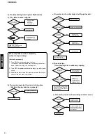
Page 12: ...ing play but time display advances properly FOCUS servo system defective YES Is FOCUS lock done IC3 or IC4 defective Microcomputer defective YES NO Feed limit switch defective Does tray load properly NO YES Is pick up at innermost position NO Poor tray loading Jitter defective YES Is EFMI signal normal NO Spindle servo system defective YES Does spindle motor run NO c Operates as if no disc loaded ...

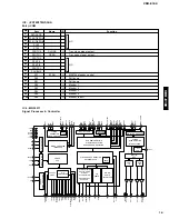
Page 13: ...10 11 12 13 14 15 16 17 18 19 20 21 22 23 24 25 26 27 Function Opened state of tray sensing switch input Opened state at L Closed state of tray sensing switch input Closed state at L N C Sound output at H and sound output muted at L Hardware reset output of MN35511 Reset at L Mute output to MN35511 Muted at H Tracking servo drawing signal input from MN35511 Drawn at L Focus servo drawing signal in...

Page 14: ...42 43 44 45 46 47 48 49 50 51 52 53 54 55 56 57 58 59 60 61 62 63 64 65 66 67 68 69 70 71 72 73 74 75 76 77 78 79 80 Port P13 ANI3 P14 ANI4 P15 ANI5 P16 ANI6 P17 ANI7 AVSS P130 ANO0 P131 ANO1 AVREF1 P70 S12 RXD P71 SO2 TXD P72 SCK2 ASCK VSS P20 SI1 P21 SO1 P22 SCK1 P23 STB P24 BUSY P25 SI0 SB0 P26 SO0 SB1 P27 SCK0 P80 A0 P81 A1 P82 A2 P83 A3 P84 A4 P85 A5 P86 A6 P87 A7 P40 AD0 P41 AD1 P42 AD2 P43A...

Page 15: ...EAVE CLV SERVO DIGITAL AUDIO INTERFACE INTER POLATION SOFT MUTING DIGITAL ATTENUATION PEAK DETECT AUTO CUE DSL PLL VCO 16k SRAM PEM L PEM R DD type DAC PLL VCO 2 8 TIMES OVER SAMPLING DIGITAL FILTER DIGITAL DE EMPHASIS SUBCODE BUFFER INPUT PORT SERVO TIMING GENERATOR A D CONVERTER 19 SMCK FCLK 49 VCOF 69 CK384 8 MDATA 7 MCLK 9 MLD 44 ARF 46 DRF 45 IREF 47 DSLF 48 PLLF 52 EFM 53 PCK RESY 67 AVDD 62...

Page 16: ...e Feed forced feed output 3 State Traverse Feed drive output Spindle motor ON signal L ON default NC Spindle motor drive signal forced mode output 3 State Spindle motor drive signal servo error signal output Kick pulse output 3 State Tracking drive output Focus drive output Reference voltage for DA output block TVD ECS TRD FOD FBAL TBAL Focus balance adjustment output Tracking balance adjustment o...

Page 17: ...er supply terminal for audio DAC Deemphasis detect signal output NC 384fs clock output At the CK384 pin output does not stop while RST L NC Xtal system when command is defaulted Signal processing system when command is switched Mode selecting terminal 5 Test mode setting terminal Normal H 5 Sub code data read clock input Sub code serial output SBCK effective when command is defaulted PACK data usa...

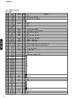
Page 18: ...11 12 13 14 15 16 17 18 19 20 21 22 23 24 25 26 27 28 29 30 Connection F1 F1 NP 14G 13G 12G 11G 10G 9G 8G 7G 6G 5G 4G 3G 2G NX NX NX NX 1G IC P35 P34 P33 P32 P31 P30 P29 P28 Pin No 31 32 33 34 35 36 37 38 39 40 41 42 43 44 45 46 47 48 49 50 51 52 53 54 55 56 57 58 59 60 Connection P27 P26 NP F2 F2 F2 F2 NP P25 P24 P23 P22 P21 P20 P19 P18 P17 P16 P15 P14 P13 NX NX NX NX P12 P11 P10 P9 P8 Pin No 61 ...

Page 19: ...T 16 OFTR 18 GND 5 VCC 23 TEBPF 22 VDET 20 VREF 1 PD 4 LDP 3 LDON 2 LD 21 LD OFF IC3 AN8806SB CD Head Amp TSD STAND BY 1 2 3 4 5 6 7 8 9 10 11 12 13 14 15 16 17 18 36 35 34 33 32 31 30 29 28 27 26 25 24 23 22 21 20 19 25K 23K 10K 10K 15K 15K 10K 10K 10K 10K 10K 10K 3 6K 10 8K VCC OP1 PA PA PA PA PA PA PA PA OP1 OP1 OP1 OP1 OP1 OP1 VREF IN VREF OUT N C GAIN 1 VCTL 1 VM 1 VM 1 GND VM 2 VM 2 VCTL 2 G...

Page 20: ...G3 G2 G1 VFL TEST VSS OSCO OSCI VDD RES CE CL DI AM32 AM31 AM30 AM29 AM28 AM27 AM26 AM25 AM24 AM23 AM22 AM21 AM20 AM19 AM18 AM17 AM1 AM2 AM3 AM4 AM5 AM6 AM7 AM8 AM9 AM10 AM11 AM12 AM13 AM14 AM15 AM16 ADDRESS REGISTER SHIFT REGISTER CONTROL BLINKCYCLE REGISTER DISPLAY REGISTER DUTYCYCLE REGISTER GRID REGISTER INSTRUCTION DECODER ADDRESS COUNTER BLINK GENERATOR DISPLAY CONTROL DUTY GENERATOR GRID CO...

Page 21: ...ON VREF 5 10 23 35 36 34 2 7 6 12 13 25 24 30 31 1 18 3 20 4 15 22 33 17 20 IC1 M56748 IC2 LB1641 5A 1 2 87 86 21 22 21 25 24 27 26 28 29 40 44 63 64 65 66 LPF IC8 LPF IC8 IC7 IC7 Q9 Q11 Q10 Q12 11 10 15 47 48 5 18 XL2 RESET IN OUT D22 4 MUTE MDATA MCLK 7 8 6 TX MDATA MCLK OUT L OUT R DIGITAL OUT OPTICAL LINE OUT 61 64 47 48 50 51 VB VB 5 5A 5 8 RESET SYSCON T1 L1 20 19 36 37 69 70 F1 F2 D10 L PJ1...

Page 22: ...SE OPEN STAN OPSW CLSW FLSW DGND VREF TRV TVD ECM ECS TD FDD ACF VF BLK CL 5 K1 KD1 ACF GND CE D1 K2 KD KD0 1 4 8 5 P C B MAIN 1 Surface Mount Device 2 1 18 1 19 36 20 1 41 60 40 61 21 80 3 0 1 5 1 8 0 5 0 8 1 3 1 1 0 0 Point w Pin 10 of IC5 V 2V div H 0 1µsec div DC 1 1 probe Point q Pin 59 of IC4 V 2V div H 50nsec div DC 1 1 probe 0V 0V PRINTED CIRCUIT BOARD Foil side E 22 J 20 ...

Page 23: ... TA FA VC E A C GND VR FA TA L L OSW GND CSW VF ACF ACF FEOF CLOSE OPEN STAN OPSW CLSW FLSW DGND VREF TRV TVD ECM ECS TD FDD DGND SYSCON DOUT ZFLG RESET L AGND R SGND 5 VREF PDF PDE A C D B LD PD 1 10 P C B MAIN 2 Surface Mount Device 4 1 8 16 9 1 4 8 5 1 18 36 19 1 4 8 5 PRINTED CIRCUIT BOARD Foil side E 25 J 23 CH 2 CH 1 Point r CH 1 Pin 7 of IC6 CH 2 Pin 16 of IC6 V 2V div CH 1 V 2V div CH 2 DC...

Page 24: ... A C G N D G N D FL FL TO MAIN 2 9 YE BR BR OR RE WH WH BR B R OR YE RE BE BE GY GY W9 G only R only J U C R A only L2 FROM POWER CORD AC OUTLET VOLTAGE SELECTOR R only P C B MAIN 3 P C B MAIN 4 PRINTED CIRCUIT BOARD Foil side E 26 J 24 CIRCUIT CHANGES BY MARKET U C R A B G J CB18 19 X X X X O X F1 X X X X O X J1 O X O O O O SW1 X O X X X X TE1 O O O X O O O USED X NOT USED Point e Pin 58 of IC10 ...

Page 25: ...5 1 9 2 2 2 2 2 5 5 0 5 0 2 6 2 5 2 5 5 0 2 2 2 2 0 0 0 0 0 0 0 5 0 2 5 0 0 5 0 7 0 7 9 9 0 7 0 5 0 9 9 0 0 2 5 0 2 5 2 5 0 3 7 1 6 3 9 3 2 3 6 3 6 2 5 2 5 2 5 24 8 24 8 24 8 24 8 24 8 24 8 24 8 24 8 24 8 24 8 24 8 24 8 24 8 24 8 21 3 21 3 21 3 21 3 0 1 4 8 0 4 4 9 4 9 2 4 2 4 0 0 27 6 24 8 24 8 24 8 24 8 24 8 24 8 24 8 24 8 24 8 24 8 24 8 24 8 24 8 24 8 5 0 0 5 0 5 0 0 0 5 0 5 0 0 5 0 5 0 4 9 10 ...

Page 26: ...NG MODULE LED DSPLY LED DISPLAY LED INFRD LED INFRARED MODUL RF MODULATOR RF PHOT CPL PHOTO COUPLER PHOT INTR PHOTO INTERRUPTER PHOT RFLCT PHOTO REFLECTOR PIN TEST PIN TEST POINT PLST RIVET PLASTIC RIVET R ARRAY RESISTOR ARRAY R CAR CARBON RESISTOR R CAR CHP CHIP RESISTOR R CAR FP FLAME PROOF CARBON RESISTOR R FUS FUSABLE RESISTOR R MTL CHP CHIP METAL FILM RESISTOR R MTL FLM METAL FILM RESISTOR R ...

Page 27: ...L 0 47uF 50V C34 UA954680 C MYLAR 0 068uF 50V C35 UB045100 C CE M CHP 0 1uF 50V C36 UB045100 C CE M CHP 0 1uF 50V C37 VJ901100 C CE M CHP 47pF 50V C38 VJ901100 C CE M CHP 47pF 50V C39 VG290600 C EL 2 2uF 50V C40 VG290600 C EL 2 2uF 50V C41 VG290600 C EL 2 2uF 50V C42 VG290600 C EL 2 2uF 50V C43 UB045100 C CE M CHP 0 1uF 50V C44 VG286500 C EL 470uF 10V C45 UB045100 C CE M CHP 0 1uF 50V C46 UB045100...

Page 28: ... R95 HL117220 R MTL OXD 22KΩ 1 2W R96 HL115330 R MTL OXD 330Ω 1 2W R97 HL115680 R MTL OXD 680Ω 1 2W R98 HL115560 R MTL OXD 560Ω 1 2W R99 HL116120 R MTL OXD 1 2KΩ 1 2W R100 HL117470 R MTL OXD 47KΩ 1 2W R102 HV755270 R CAR FP 270Ω 1 4W Z R103 V2370600 R FUS 0 47Ω 1 6W R105 HL115330 R MTL OXD 330Ω 1 2W R106 HL115390 R MTL OXD 390Ω 1 2W R111 HL115330 R MTL OXD 330Ω 1 2W R112 HL115390 R MTL OXD 390Ω 1 ...

Page 29: ...s attached to the fluorescent character display tube When a GD type main PCB becomes necessary order a SI type main PCB and a GD type sheet FL VQ948800 and replace the sheet FL of the SI type main PCB with the GD type sheet FL 101 150 122 150 142 142 11 12 103 3 4 146 3 145 145 3 3 2 17 16 102 145 120 120 120 142 148 110 148 149 149 110 121 143 140 140 142 106 15 107 152 1 1 3 151 104 142 1 20 1 1...

Page 30: ...ONNECTOR FLAT CABLE 16P 230mm 16 MF705100 CONNECTOR ASS Y 5P 100mm 17 MF706100 CONNECTOR ASS Y 6P 100mm 101 V3681700 TOP COVER SI 101 V3809200 TOP COVER GD 102 V3684500 CHASSIS 103 V3682700 REAR PANEL UC 103 V3682800 REAR PANEL R 103 V3682900 REAR PANEL A 103 V3683000 REAR PANEL B 103 V3683100 REAR PANEL G 104 V3684600 FRAME MECH CDX 106 V3687200 LID CDX SI 106 V3810900 LID CDX GD 107 VZ262200 SUP...

Page 31: ...The stopper is not supplied with the tray as a spare part When replacing the tray keep the removed stopper and reuse it Should it be lost and a new one be necessary order service part 8 Main Chassis S and remove the stopper only from it and use it as a spare part Stopper ...

Page 32: ...650 SUB CHASSIS ASS Y S 264628801 12 AX624640 COIL SPRING F 264723601 13 AX624630 COIL SPRING R 262723501 14 AX624660 WASHER 2130 264628901 15 EX604270 P TITE SCREW 2 6x10 768513511 16 AX624620 INSULATOR 262723401 18 AX619160 MAIN CHASSIS S OUTSERT 262555206 19 VH554700 BW HEAD P TITE SCREW 2 6x16 331950151 20 CX675270 DRIVE GEAR S 262554701 21 CX675260 CONTROL CAM S 262554504 22 KX604780 LEAF SWI...

Page 33: ...OR GEAR ASS Y X26257691 3 AX623980 SLED SHAFT 262690801 4 CX679720 GEAR A S 262690701 5 EA020036 PAN HEAD SCREW 2x3 ZMC2 Y 762125515 6 KX604660 LEAF SWITCH 157208511 7 NX613040 PWB MOTOR MOTOR 6P 163967812 8 LX610120 CONNECTOR PIN 6P 156472211 9 CX680030 GEAR 262700301 10 NX636020 OPTICAL HEAD KSM213C Note The parts marked with an asterisk are not available separately Cover ...

Page 34: ...HF45 4100 HF85 4150 HF45 4220 HF85 4270 HF45 4330 HF85 4390 HF45 4470 HF45 4560 HF45 4680 HF45 4750 HF45 4820 HF45 4910 HF45 5100 HF85 5110 HF45 5120 HF45 5150 HF45 5180 HF45 5200 HF45 5220 HF45 5270 HF45 5330 HF45 5390 HF45 5430 HF45 5470 HF45 5510 HF45 5560 HF45 5680 HF45 5820 HF45 5910 HF45 6100 HF45 6120 HF45 6150 HF45 6180 HF85 6200 HF45 6220 HF85 6240 HF45 6270 HF45 6300 HF45 6330 HF85 6360 ...

Page 35: ...CDX E100 ...
Reviews: