


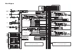

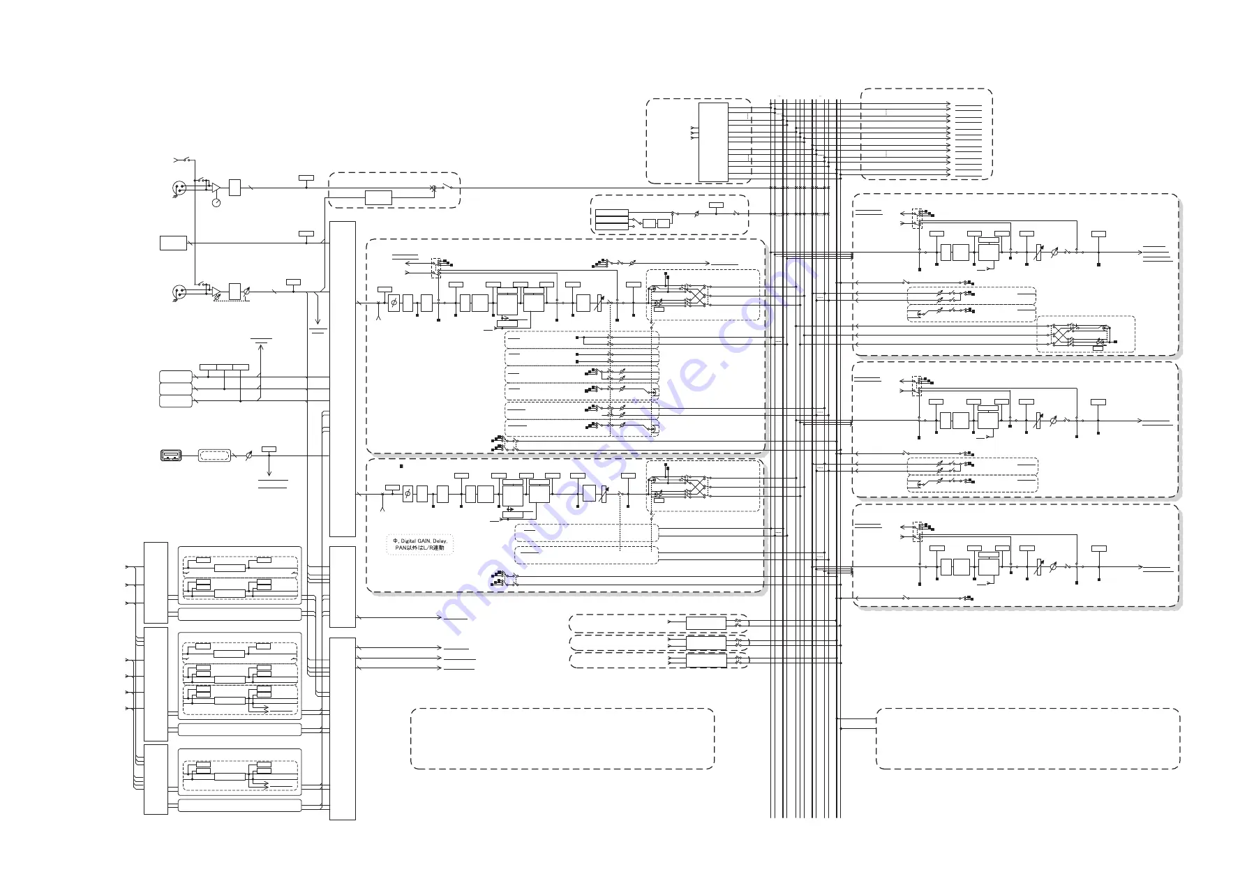
Block Diagram
INSERT IN
PATCH
(OUTPUT CH)
2
POST ON
INSERT OUT
PREMIUM
RACK IN
PATCH
EFFECT
RACK IN
PATCH
64
CASCADE
IN
SELECT
SLOT1 1-16
SLOT2 1-16
SLOT3 1-16
ATT
Keyin
Self PRE EQ
Self POST EQ
MIX21-24 OUT
CH[1-8,9-16,17-24,25-32,33-40,41-48, 49-56, 57-64, 65-72]POST EQ(U3)
CH[1-8,9-16,17-24,25-32,33-40,41-48, 49-56, 57-64]POST EQ(U5)
CH[1-8,9-16,17-24,25-32,33-40,41-48]POST EQ(U7)
ON
4BAND
EQ
GATE
DUCK
EXPAND
COMP
GR METER
COMP
COMPAND
DE-ESSER
KEYIN CUE
HPF
PRE HPF
POST EQ
INSERT
METER
LEVEL/
DCA1-16
PRE FADER
PRE FADER
POST ON
PRE FADER
INSERT OUT
PRE EQ
INSERT OUT
To OUTPUT PATCH
PRE EQ
INSERT POINT
POST ON INSERT OUT
PRE FADER INSERT OUT
PRE EQ INSERT OUT
GR METER
METER
POST ON
METER
DYNA2OUT
METER
DYNA1OUT
METER
EQ OUT
METER
PRE EQ
PRE HPF / PRE EQ / PRE FADER/POST ON
ON
LEVEL
DIRECT OUT 1-72{64,48}
To OUTPUT PATCH
PAN LINK
MATRIX1,3...7
MATRIX2,4...8
CUE R
TB INPUT
METER
HA
MIX1,3...23
MIX2,4...24
CUE L
Keyin Filter
CH INSERT IN
1-72{43,48}
To RACKIN PATCH
To OUTPUT PATCH
To RACKIN PATCH
(21-24)To KEYIN
To MONITOR SELECT
ATT
4BAND
EQ
COMP
COMPAND
EXPAND
INSERT
POST EQ
LEVEL
PRE EQ
INSERT OUT
PRE EQ
GR METER
METER
DYNA OUT
METER
EQ OUT
METER
PRE EQ
Keyin
Self PRE EQ/Self POST EQ/MIX21-24 OUT/
MIX(1-8,9-16,17-24) POST EQ
PRE FADER
CUE ON
(PRE FADER)PFL / (POST ON)AFL
INSERT
MIX 1-24
CH 1-72{64,48}
72
{64,
48}
MATRIX 1-8
CASCADE OUT
CASCADE IN
To MONITOR
SELECT
TALKBACK
INPUT
SELECT
ON
DANTE IN 1-64
OMNI IN 1-8
(PRE FADER)PFL / (POST ON)AFL / POST PAN L
ON
ON
ST L
MONO(C)
ST R
MIX
1 2
2324
ST
L R
M
O
N
O
(C)
MATRIX
1 2
7 8
CUE
L R
To OUTPUT PATCH
To OUTPUT PATCH
To OUTPUT PATCH
To OUTPUT PATCH
To OUTPUT PATCH
To OUTPUT PATCH
To OUTPUT PATCH
To OUTPUT PATCH
To OUTPUT PATCH
CUE CASCADE OUT LR
STEREO CASCADE OUT L,R,MONO(C)
MIX CASCADE OUT1-24
MATRIX CASCADE OUT1-8
To OUTPUT PATCH
To OUTPUT PATCH
To OUTPUT PATCH
To OUTPUT PATCH
METER
PRE HPF
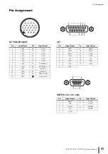
+48V
+48V MASTER
+48V
AD
[TALKBACK
INPUT]
TALKBACK
INPUT
TALKBACK
GAIN
ON
1
2
3
+
-
+48V
AD
[OMNI IN]
[1-8]
OMNI IN
+
-
1
2
3
METER
HA
CH INSERT OUT
1-72{64,48}
PRE EQ / PRE FADER / POST ON
ON
LEVEL
ON
LEVEL
LEVEL
PAN
ON
PRE EQ / PRE FADER / POST ON
To MATRIX
VARI
To MATRIX
VARI
STEREO
PRE EQ / PRE FADER / POST ON
ON
LEVEL
ON
LEVEL
LEVEL
PAN
ON
PRE EQ / PRE FADER / POST ON
To MIX
VARI
To MIX
VARI
STEREO
To MIX
FIXED
POST ON
ON
ON
To MIX
FIXED
STEREO
POST PAN L
POST PAN R
ON
ON
MIX INSERT IN 1-24
STEREO INSERT IN L,R,MONO(C)
24
3
CH INSERT IN 1-72{64,48}
MATRIX INSERT IN 1-8
8
LEVEL
ON
Pink Noise
Burst Noise
HPF LPF
METER
OSC
OSCILLATOR
Sine Wave
Refer to CL5/CL3/CL1 Mixer Block Diagram 2/2
INPUT
PATCH
DANTE IN
1-64
OMNI IN
1-8
SLOT3 1-16
SLOT2 1-16
SLOT1 1-16
STEREO OUT
L,R,MONO(C)
CH
INSERT OUT
1-72{64,48}
MIX
INSERT OUT
1-24
STEREO
INSERT OUT
L,R,MONO(C)
MATRIX
INSERT OUT
1-8
GEQ
RACK IN
PATCH
GEQ1 IN
A(L)/B(R)
GEQ2-16 IN
A(L)/B(R)
FX1 IN
A(L)/B(R)
FX2-8 IN
A(L)/B(R)
INSERT IN
PATCH
(INPUT CH)
FX1 OUT
A(L)/B(R)
FX2-8 OUT
A(L)/B(R)
PFX1-8 OUT
A(L)/B(R)
FX1-8 OUT
A(L)/B(R)
GEQ RACK1(GEQ1)
Flex15GEQ
METER RACK IN A
METER RACK IN B
METER RACK OUT A
METER RACK OUT B
GEQ RACK2-16(GEQ2-16) (same as GEQ RACK1)
EFFECT RACK2-8(FX2-8) (same as EFFECT RACK1)
EFFECT RACK1(FX1)
EFFECT
METER RACK IN L
METER RACK IN R
METER RACK OUT L
METER RACK OUT R
Flex15GEQ
METER RACK IN A
METER RACK IN B
METER RACK OUT A
METER RACK OUT B
EFFECT CUE
PAN
TO ST
LR MONO
TO MONO
LCR
TO LCR
CSR
POST PAN L
POST PAN R
(PRE FADER)PFL / (POST ON)AFL / POST PAN R
EFFECT CUE
SELECT
PFX1-8 OUT L/R
EFFECT CUE
ON
KEYIN CH1-72
KEYIN CUE
KEYIN CUE
SELECT
ON
ON
POST ON
METER
POST ON
MIX OUT1-24
INSERT
METER
PRE FADER
PRE FADER
INSERT OUT
To OUTPUT PATCH
MIX
INSERT IN 1-24
To RACKIN PATCH
MIX
INSERT OUT 1-24
ST L
MONO(C)
ST R
ON
LEVEL
ON
LEVEL
LEVEL
PAN/BAL
ON
To MATRIX
VARI
To MATRIX
VARI
STEREO
MATRIX1,3...7
MATRIX2,4...8
CUE ON
(PRE FADER)PFL / (POST ON)AFL
To OUTPUT PATCH
To MONITOR SELECT
ATT
4BAND
EQ
COMP
COMPAND
EXPAND
INSERT
POST EQ
LEVEL
PRE EQ
INSERT OUT
PRE EQ
GR METER
METER
DYNA OUT
METER
EQ OUT
METER
PRE EQ
Keyin
Self PRE EQ/Self POST EQ/MIX21-24 OUT/
ST(L,R,MONO(C)) POST EQ
PRE FADER
STEREO L,R,MONO(C)
ON
POST ON
METER
POST ON
STEREO OUT
L,R,MONO(C)
INSERT
METER
PRE FADER
BAL
PRE FADER
INSERT OUT
To OUTPUT PATCH
STEREO
INSERT IN L,R,MONO(C)
To RACKIN PATCH
STEREO
INSERT OUT L,R,MONO(C)
To OUTPUT PATCH
To MONITOR SELECT
ATT
4BAND
EQ
COMP
COMPAND
EXPAND
INSERT
POST EQ
LEVEL
PRE EQ
INSERT OUT
PRE EQ
GR METER
METER
DYNA OUT
METER
EQ OUT
METER
PRE EQ
Keyin
Self PRE EQ/Self POST EQ/MIX21-24 OUT/
MATRIX1-8 POST EQ
PRE FADER
ON
POST ON
METER
POST ON
MATRIX OUT 1-8
INSERT
METER
PRE FADER
PRE FADER
INSERT OUT
To OUTPUT PATCH
MATRIX
INSERT IN 1-8
To RACKIN PATCH
MATRIX
INSERT OUT 1-8
CUE ON
(PRE FADER)PFL / (POST ON)AFL
PAN MODE
GAIN/TRIM
PAN/BAL
TO ST
LR MONO
TO MONO
LCR
TO LCR
CSR
POST ON
PAN MODE
PRE FADER / POST ON
PRE FADER / POST ON
PRE FADER / POST ON
31BandGEQ
METER RACK IN
METER RACK OUT
31BandGEQ
METER RACK IN
METER RACK OUT
SLOT1 1-16
SLOT2 1-16
SLOT3 1-16
To MATRIX INSERT IN
To STEREO INSERT IN
To MIX INSERT IN
To CH INSERT IN
PRE FADER / POST ON
ON
LEVEL
ON
LEVEL
LEVEL
PAN/BAL
ON
To MATRIX
VARI
To MATRIX
VARI
STEREO
MATRIX1,3...7
MATRIX2,4...8
PFX1-2 OUT
A(L)/B(R)
FX1-8 OUT
A(L)/B(R)
To CASCADE IN
SELECT
[SLOT]
SLOT1
SLOT2
SLOT3
METER
SLOTIN
16
16
16
METER
SLOTIN
METER
SLOTIN
72
MATRIX OUT
1-8
MIX OUT
1-24
OUTPUTS
[DANTE]
DANTE
INPUT
METER
DANTE
IN
DELAY
Max
1000ms
INSERT
POST ON
INSERT OUT
PFX1 IN
A(L)/B(R)
PFX2-8 IN
A(L)/B(R)
PFX1 OUT
A(L)/B(R)
PFX2-8 OUT
A(L)/B(R)
PREMIUM RACK2-8 (same as PREMIUM RACK1)
PREMIUM EFFECT RACK1(PFX1)
EFFECT
METER RACK IN L
METER RACK IN R
METER RACK OUT L
METER RACK OUT R
EFFECT CUE
FX1-8 OUT L/R
INSERT
INSERT POINT
POST ON INSERT OUT
PRE FADER INSERT OUT
PRE EQ INSERT OUT
INSERT POINT
POST ON INSERT OUT
PRE FADER INSERT OUT
PRE EQ INSERT OUT
POST ON
INSERT OUT
INSERT
POST ON
INSERT OUT
INSERT
INSERT POINT
POST ON INSERT OUT
PRE FADER INSERT OUT
PRE EQ INSERT OUT
RECORDER CUE
SELECT
PLAYBACK OUT L/R
RECORDER CUE
ON
RECORDER INL/R
To MONITOR SELECT
METER
PLAYBACK OUT
RECORDER CUE
USB
[PLAYBACK
OUT]
GAIN
DECODER
Refer to CL5/CL3/CL1 Mixer Block Diagram 2/2
CUE / MONITOR
16
ON
METER
LEVEL/
DCA1-16
PRE FADER
PRE FADER
POST ON
METER
POST ON
PAN LINK
MATRIX1,3...7
MATRIX2,4...8
CUE R
MIX1,3...23
MIX2,4...24
CUE L
(PRE FADER)PFL / (POST ON)AFL / POST PAN L
ON
ON
ST L
MONO(C)
ST R
To MATRIX
To MIX
SAME as INPUT1-72{64,48}
PAN/BAL
TO ST
LR MONO
TO MONO
LCR
TO LCR
CSR
POST PAN L
POST PAN R
(PRE FADER)PFL / (POST ON)AFL / POST PAN R
PAN MODE
ST IN 1L 8R
Digital
GAIN
Keyin
Self PRE EQ
Self POST EQ
MIX21-24 OUT
ST IN 1L-4R POST EQ
4BAND
EQ
GATE
DUCK
EXPAND
COMP
GR METER
COMP
COMPAND
DE-ESSER
KEYIN CUE
HPF
PRE HPF
POST EQ
PRE EQ
GR METER
METER
DYNA2OUT
METER
DYNA1OUT
METER
EQ OUT
METER
PRE EQ
Keyin Filter
METER
PRE HPF
DELAY
Max
1000ms
SAME as INPUT1-72{64,48}
SLOT1 1-16
SLOT2 1-16
SLOT3 1-16
GEQ1-16
OUT
A(L)/B(R)
8
1
Digital
GAIN
ATT
OMNI IN 1-8
OMNI IN 1-8
OSCILLATOR
OSCILLATOR
BAL
BAL
Summary of Contents for CL3
Page 1: ...EN Owner s Manual Keep This Manual For Future Reference...
Page 60: ......


