background image

  V1.7 Supplementary Manual

25

OUTPUTS

PHONES OUT LR

[PHONES]

DA

PHONES LEVEL

2

Tip

Ring

Sleeve

OUTPUT 

PATCH

SLOT1

SLOT2

SLOT3

[SLOT]

1 6

1 6

1 6

METER

SLOT1OUT

METER

SLOT2OUT

METER

SLOT3OUT

DELAY

(MAX:1000ms)

DELAY

(MAX:1000ms)

DELAY

(MAX:1000ms)

DA

[OMNI OUT] (1-8)

8

+

-

1

2

3

METER OMNI OUT

DELAY

(MAX:1000ms)

TRIM

GAIN

OUTPUT 

PATCH

2

DIT

[DIGITAL OUT]

AES/EBU

DELAY

(MAX:1000ms)

METER

DIGITAL 

OUT

TRIM

GAIN

TRIM

GAIN

[DANTE OUT] (1-64)

6 4

METER DANTE OUT

DELAY

(MAX:1000ms)

GAIN

OUTPUT 

PATCH

DANTE

OUTPUT

MIX CASCADE OUT 1-24

STEREO CASCADE OUT L,R,MONO(C)

MATRIX CASCADE OUT 1-8

CUE CASCADE OUT L,R

DIRECT OUT 1-72{64,48}

MATRIX OUT 1-8

MIX OUT 1-24

STEREO OUT L,R,MONO(C)

MONITOR OUT L,R,MONO(C)

CUE OUT L,R

CH INSERT OUT 1-72{64,48}

MIX INSERT OUT 1-24

STEREO INSERT OUT L,R,MONO(C)

MATRIX INSERT OUT 1-8

2

RECORDER CUE

GAIN

METER

RECORDER IN

OUTPUT 

PATCH

ENCODER

[2TR RECORDER]

OUTPUT 

PATCH

MONITOR L
MONITOR R
MONITOR MONO(C)

MONITOR OUT MONO(C)

MONITOR OUT R

MONITOR OUT L

To OUTPUT PATCH

To OUTPUT PATCH

To OUTPUT PATCH

MONO

METER MONITOR R

METER MONITOR MONO(C)

TALKBACK ON

METER MONITOR L

CUE TRIM

(INPUT/OUTPUT/DCA)

CUE L
CUE R

MONO

METER CUE L

METER CUE R

ON

MONITOR

LEVEL

DIM

M

E

R

MONITOR DIMM ON

CUE LOGIC

+MONO(C)

MO

NITOR

 SELECT

MATRIX OUT1-8

MIX OUT1-24

OMNI IN 1/2

DEFINE

MIX

(MAX:8ch)

OMNI IN 3/4
OMNI IN 5/6
OMNI IN 7/8

STEREO OUT L,R

STEREO OUT MONO(C)

STEREO OUT L,C,R

PHONES L

PHONES R

To PHONES OUT

To PHONES OUT

DELAY

(MAX:1000ms)

DELAY

(MAX:1000ms)

PHONES 

LEVEL LINK

An output port delay becomes invalid by 

assigning a monitor out to the output port.

CUE OUT L

CUE OUT R

To OUTPUT PATCH

To OUTPUT PATCH

CUE OUT ON

PLAYBACK OUT

OMNI IN 1/2
OMNI IN 3/4
OMNI IN 5/6
OMNI IN 7/8
PLAYBACK OUT

STEREO OUT L,R

STEREO OUT MONO(C)

CUE L BUS

CUE R BUS

CUE / MONITOR

STEREO L

MONO(C)

STEREO R

DELAY

(MAX:1000ms)

DELAY

(MAX:1000ms)

DELAY

(MAX:1000ms)

MONITOR

FADER

CUE INTERRUPTION

CUE ON

DELAY

(MAX:1000ms)

DELAY

(MAX:1000ms)

ON

MONITOR DELAY AUTO BYPASS

CUE OUT

LEVEL

USB

1

2

3

4

Summary of Contents for CL5

Page 1: ...tary Manual This supplementary manual explains mainly the functions that have been added or changed in CL5 CL3 CL1 firmware V1 6 and V1 7 Use it in conjunction with the CL5 CL3 CL1 Owner s Manual and...

Page 2: ...10 Added functions for meter display 10 Graphic EQ Effects and Premium Rack 11 Improvements in popup window operation 11 Improved display for tap tempo function 11 I O device and external head amp 12...

Page 3: ...is assigned to the GAIN knob the digital gain value is shown here The GAIN knob 48V indicator and HPF ON indicator are not shown if an input without a head amp is patched to the input channel D GAIN...

Page 4: ...ead amp The HPF EQ popup screen now shows an HPF ON indicator and the cutoff frequency 1 HA HPF ON indicator Indicates the HPF on off status of the external head amp 2 FREQUENCY Indicates the HPF cuto...

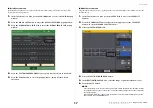
Page 5: ...CT popup window 1 In the OVERVIEW screen press the GAIN PATCH field to access the GAIN PATCH popup window 2 Press the PATCH button or INPUT PORT button to access the PORT SELECT popup window 3 Press a...

Page 6: ...be specified NOTE If you re newly patching a previously unpatched input channel the default values will be specified if the HA INFO field s TAKE FROM CHANNEL button is pressed Settings in the PATCH NA...

Page 7: ...and displaying DCA group names 1 In the Function Access Area press the CH JOB button 2 Press the DCA GROUP button to access the DCA MUTE GROUP ASSIGN MODE popup window 1 NAME EDIT button Edits the gr...

Page 8: ...ctions for DCA groups Sends from an input channel to a bus whose send point is set to PRE can now be assigned to be muted by a DCA group 1 POST ONLY button Specifies the object of muting as POST only...

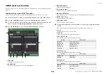
Page 9: ...eys or the channel display field to select the channels that you want to link the link indicator will show the link group If a channel belonging to a link group is selected the associated link group i...

Page 10: ...NITOR screen 2 Press the CUE popup display button Use the knob to adjust the monitor level in the range of 30 dB 20 dB Meters Added functions for meter display PRE GC METER and POST DIGITAL GAIN METER...

Page 11: ...lf POST EQ MIX21 24 OUT CH 1 8 9 16 17 24 25 32 33 40 41 48 49 56 57 64 65 72 POST EQ CL5 CH 1 8 9 16 17 24 25 32 33 40 41 48 49 56 57 64 POST EQ CL3 CH 1 8 9 16 17 24 25 32 33 40 41 48 POST EQ CL1 ON...

Page 12: ...r to verify the status of an R series unit from the console it must be assigned to REMOTE HA in DANTE SETUP CL series The SETUP field of the DANTE SETUP screen shows indicators for the status of the C...

Page 13: ...act your Yamaha dealer for repair The MAC address setting has been corrupted and no communication can occur via Dante The internal memory has been corrupted Use the front panel DIP switches to set STA...

Page 14: ...EVICE SELECT popup window shows the device label and device type SYNC Indicators Description Possible Solution A non GbE compatible device is connected When transferring audio via Dante use device tha...

Page 15: ...fader bank settings can now be stored recalled for individual scenes Custom fader bank settings are separated into areas for each model and stored together in the scene data NOTE Custom fader bank set...

Page 16: ...ess the FOCUS tab at the bottom of the SCENE LIST window Custom bank settings are included in OTHER PARAMs 3 Press the SET button of the scene for which you want to make settings the FOCUS RECALL popu...

Page 17: ...The global paste function lets you copy and paste the custom bank settings of the current scene to scene data in memory 1 In the Function Access Area press the SCENE field to access the SCENE LIST wi...

Page 18: ...he data shown in the field 5 MULTI SELECT button By pressing this button you can make a selection containing multiple items of data 6 SELECT ALL button Press this button to select all items 7 CLEAR AL...

Page 19: ...ress the SAVE LOAD button to access the SAVE LOAD popup window 3 If necessary press the directory icon and change the directory 4 Press the SAVE button to access the SAVE SELECT popup window 1 TYPE fi...

Page 20: ...annel settings Items that are included in the ADMIN tab when loading items individually will be included in ALL when saving 6 In the SOURCE field add a check mark to select the data that you want to s...

Page 21: ...th the USB device was stopped because an overcurrent condition occurred at the USB port it is now possible to reconnect the USB device without restarting Recovery procedure After removing the cause of...

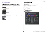
Page 22: ...window the channel number is now shown Added channel color Black can now be specified as a channel color If black is selected for a channel its channel color indicator will be unlit Make this setting...

Page 23: ...ected UNLATCH a switch that is on only while pressed and is off when released is selected Initializing the Dante audio network settings It is now possible for Dante related settings to also be initial...

Page 24: ...AFL POST PAN R EFFECT CUE SELECT PR1 8 OUT L R EFFECT CUE ON KEYIN CH1 72 64 48 KEYIN CUE KEYIN CUE SELECT ON ON POST ON METER POST ON MIX OUT1 24 INSERT METER PRE FADER PRE FADER INSERT OUT To OUTPU...

Page 25: ...ONITOR R MONITOR MONO C MONITOR OUT MONO C MONITOR OUT R MONITOR OUT L To OUTPUT PATCH To OUTPUT PATCH To OUTPUT PATCH MONO METER MONITOR R METER MONITOR MONO C TALKBACK ON METER MONITOR L CUE TRIM IN...

Page 26: ...310IP A0 2013 Yamaha Corporation C S G PA Development Division Yamaha Manual Library http www yamaha co jp manual Yamaha Pro Audio Global Web Site http www yamahaproaudio com...

Reviews: