16
CLP-340/CLP-340M/CLP-340C
<Top view>
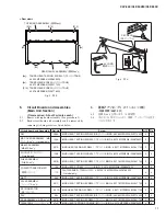
[23]: FLAT WASHER
(平座小型丸)
4.0X8X0.8 MFZN2W3 (WF57860R)
[S01G]: BIND HEAD TAPPING SCREW-1
(
TP
#
1
+
BIND
)
3.5X11 MFZN2W3 (WF831100)
[S05]: BIND HEAD TAPPING SCREW-1
(
TP
#
1
+
BIND
)
4.0X14 MFZN2W3 (WE97190R)
[S06]: PAN HEAD SCREW
(小ネジ+PAN)
5.0X25 MFZN2W3 SW (WF00150R)
[S13]: BIND HEAD TAPPING SCREW-B
(Bタイト+BIND)
4.0X10 MFZN2W3 (WE97450R)
[S14]: BIND HEAD TAPPING SCREW-B
(Bタイト+BIND)
4.0X20 MFZN2B3 (WE96210R)
CONTROL PANEL ASSEMBLY
(パネルAss'y)
KEY BLOCK ASSEMBLY L
(拍子木Ass'y (L))
KEY BLOCK ASSEMBLY R
(拍子木Ass'y (R))
KEYBOARD ASSEMBLY
(GH3鍵盤)
[S06]
[S06]
[S06]
[S06]
[S06]
[S01G]
[S01G]
[S01G]
[S01G]
[S01G]
[S01G]
[S01G]
[S05]
[S06]
[S06]
[S05]
[S13]
[S14]
[23]
[S13]
[S14]
[23]
11.
Control Panel Assembly
(Time required: About 3 minutes)
11-1 Remove the top board assembly. (See procedure 3)
11-2 Remove the key cover assembly. (See procedure 9)
11-3 Remove the seven (7) screws marked [S01G] and
the two (2) screws marked [S13]. The control panel
assembly can then be removed. (Fig. 8)
12.
Key Block Assembly (L, R)
(Time required: About 3 minutes each)
12-1 Remove the top board assembly. (See procedure 3)
12-2 Remove the key cover assembly. (See procedure 9)
12-3 Remove the control panel assembly.
(See procedure 11)
12-4 Remove the screw marked [S14] and the fl at washer
marked [23]. The key block assembly L can then be
removed. (Fig. 8)
*
The left and right key block assembly can then be
removed in the same manner.
11.
パネル Ass y
(所要時間:約 3 分)
11-1
屋根 Ass y を外します。
(3 項参照)
11-2
スライド蓋 Ass y を外します。
(9 項参照)
11-3
[S01G] のネジ 7 本と [S13] のネジ 2 本を外して、パ
ネル Ass y を外します。
(図 8)
12.
拍子木 Ass y(L・R)
(所要時間:各約 3 分)
12-1
屋根 Ass y を外します。
(3 項参照)
12-2
スライド蓋 Ass y を外します。
(9 項参照)
12-3
パネル Ass y を外します。
(11 項参照)
12-4 [S14] のネジ 1 本と [23] の平座小型丸 1 個を外して、
拍子木 Ass y(L)を外します。
(図 8)
※
拍子木 Ass y(R)も同様に外すことができます。
Fig. 8(図 8)

