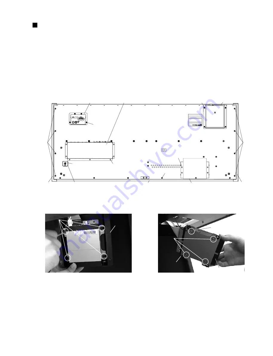
2.
Mic. & Phones Unit, MIC Circuit Board,
HP Circuit Board
(Time required: About 10 minutes)
2-1
Remove the four (4) screws marked [50B]. The mic. &
phones unit can then be removed. (Fig. 1)
2-2
Remove the input volume knob and the hexagonal nut marked
[40A]. The MIC circuit board can then be removed. (Fig. 4)
2-3
Remove the two (2) hexagonal nuts marked [40B]. The
HP circuit board can then be removed. (Fig. 4)
[8A]
[3A]
[3B]
FDD cover
FDD holder
GND Wire
GND Wire
FDD
Fig. 1
Fig. 2
[15]: Truss Head Tapping Screw-1 3.5x25 MFZN2BL (EN630190)
[35c]: Bind Head Tapping Screw-B 3.0x8 MFZN2BL (EP600190)
[50]: Bind Head Tapping Screw-1 3.5x14 MFZN2BL (EP030250)
[8A]: PW Head Tapping Screw-B 3.0x8-8 MFZN2BL (V2276900)
Fig. 3
[3]: Bind Head Screw 3.0x5 MFZN2Y (EG330150)
• Bottom view
FDD unit
Mic. & phones unit
Jack unit
[50A] x 4
PK connector assembly
Arm assembly L
Arm assembly R
FU assembly
[50B] x 4
[71] x 7
[35c]
[15A]
[112] x 4
[15B] x 6
Back top board assembly
[15A]
DISASSEMBLY PROCEDURE
CVP-205/CVP-205M
10
1.
Floppy Disk Drive
(Time required: About 10 minutes)
1-1
Remove the four (4) screws marked [50A]. The FDD unit
can then be removed. (Fig. 1)
1-2
Remove the four (4) screws marked [8A]. The FDD cover
can then be removed. (Fig. 2)
1-3
Remove the screw marked [3A]. The earth wire can then
be removed. (Fig. 3)
1-4
Remove the three (3) screws marked [3B]. The floppy disk
drive can then be removed from the FDD holder. (Fig. 3)
Summary of Contents for Clavinova CVP-103M
Page 34: ...CVP 205 CVP 205M 34 DM Circuit Board 2NA V716590 2 2 Pattern side ...
Page 37: ...B B PNR Circuit Board CVP 205 CVP 205M 37 2NA V713520 2 1 ...
Page 38: ...ENC Circuit Board B B CVP 205 CVP 205M 38 Pattern side Pattern side 1 PNR ENC 2NA V713520 2 ...
Page 43: ...to DM CN10 SWX Circuit Board CVP 205 CVP 205M 43 2NA V716050 1 Pattern side Component side ...
Page 100: ...CVP 205 CVP 205M 24 SIDE BOARD ASSEMBLY Top view Side view 1 9 8 6 6a 6b 11 7 7 4 2 3 5 ...


