


6
MY16-C
Owner’s Manual
ENGLISH
■
Conductor and Performers
On any CobraNet network one device generates a timing signal that all other devices receive and
are synchronized to. The device that generates the synchronization signal is known as the
“conductor,” while all other devices are “performers.”
The conductor for the network is automatically assigned and need not be specified by the operator.
When an MY16-C is assigned to be the conductor for the network, the LED indicator to the right of
the connector that is connected to the network will light orange. If the conductor fails for some
reason, conductor status is automatically switched to another device on the network.
Since the conductor transmits the synchronization signal to the performers via the network cable,
no separate word clock cables are required and the total number of cables used by the system is
kept to a minimum. Digital audio devices that are not connected to the network, however, will need
to receive a word clock signal from a device on the network in order to achieve synchronization.
n
Digital signals and control data are transmitted and received by all conductor and performer
devices on the CobraNet network.
■
CobraNet Cables and Hubs
Category-5 metal cables can be used for runs of up to 100 meters, while multimode optical fiber
cables can be used for runs of up to 2 kilometers.
“Cross” and “straight” Ethernet cables are available. “Cross” cables should be used for direct
connection between two devices. Hubs and "straight" cables are required to connect 3 or more
devices. Ethernet hubs are available in “repeater” and "switching" configurations. Switching hubs
are recommended for use on CobraNet networks. The use of repeater hubs can result in excessive
network traffic, thus reducing network efficiency.
It is best to use a repeater hub that has been tested and certified by Peak Audio.
A list is available at
http://www.peakaudio.com/cobranet/tested_ethernet.html.
E
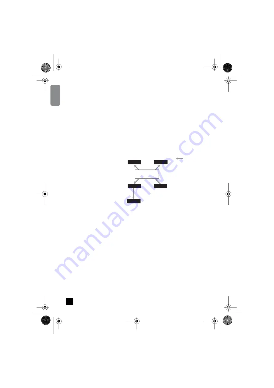
Sync (Word Clock)
Performer (Receive)
Performer (Receive)
Performer
(Receive)
Conductor
(Transmit)
C
B
A
D
Network
External Digital Device
Conductors transmit the synchronization
signal that is received and used by
performers. Clock synchronization is
necessary to transfer digital audio data to
and from devices outside the CobraNet
network. In this example device B on the
CobraNet network sends the synchronization
signal to external device E.
4
MY16-C_E.book Page 6 Tuesday, April 13, 2004 7:32 PM


