8
MY16-C
Owner’s Manual
ENGLISH
■
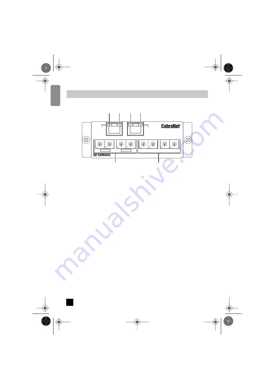
Panel Connectors and Switches
1
[PRIMARY] and
2
[SECONDARY] Connectors
These are 100Base-T Ethernet connectors. The MY16-C provides two Ethernet connectors to
allow construction of redundancy networks employing dual (primary and secondary) circuits. The
[PRIMARY] connector is for connection to the main circuit, while the [SECONDARY] connector is
for connection to the backup circuit.
If a failure occurs on the PRIMARY circuit (e.g. a cable failure, accidental disconnection, switching
hub failure, etc.) the SECONDARY circuit will automatically take over. Basic redundancy network
setup is described on page 17.
Use STP (Shielded Twisted Pair) cables to protect against electromagnetic interference.
3
[LINK/FAULT] Indicators
These are the LED indicators to the left of the [PRIMARY] and [SECONDARY] connectors.
These indicators will light when a network cable is connected to the corresponding connector. The
indicator for each connector will light green when a network cable is properly connected, and will
flash while data is being properly transferred via the corresponding connector. If an error occurs on
the connected network, the appropriate indicator will light or flash red.
If an indicator lights or flashes red, try disconnecting it from the corresponding Ethernet connector.
The indicator will go out if a cable, hub, or other device connected to the network has failed. If the
indicator remains lit or flashing even after the cable is disconnected, there may be a fault in the
MY16-C card itself. In this case please refer the problem to qualified Yamaha service personnel.
4
[IN USE/CONDUCT] Indicators
These are the indicators to the right of the [PRIMARY] and [SECONDARY] connectors. These
indicators will light when power has been properly applied to the MY16-C card. These indicators
normally light green, but will light orange when the MY16-C is operating as the
network conductor.
Controls & Functions
CobraNet INTERFACE CARD
MODEL MY16-C
MADE IN JAPAN
BUNDLE ASSIGNMENT
PRIMARY
SECONDARY
IN 1
IN 2
OUT 1
OUT 2
Gr-LINK
Rd-FAULT
Gr-IN USE
Or-CONDUCT
0
8
F
7
E
6
D
5
C
4
B
3
A
2
9
1
0
8
F
7
E
6
D
5
C
4
B
3
A
2
9
1
0
8
F
7
E
6
D
5
C
4
B
3
A
2
9
1
0
8
F
7
E
6
D
5
C
4
B
3
A
2
9
1
0
8
F
7
E
6
D
5
C
4
B
3
A
2
9
1
0
8
F
7
E
6
D
5
C
4
B
3
A
2
9
1
0
8
F
7
E
6
D
5
C
4
B
3
A
2
9
1
0
8
F
7
E
6
D
5
C
4
B
3
A
2
9
1
1
2
6
5
3
4
3
4
6
MY16-C_E.book Page 8 Tuesday, April 13, 2004 7:32 PM


