background image

For  Service  Engineer 

Service Information 

SI1604009E-002= S20, S10, M20, M10 and D10 installation procedures 

5/34 

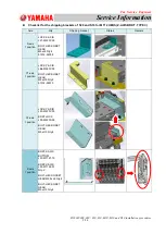
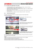
3.  Carry in machines & equipment and level the machine 

3.1  Confirmations before carrying-in 

A transport company will bring the machine to the customer’s site by truck, etc. 
The followings are the required confirmations before unloading the machines or equipment from a truck. 


Make sure there is no damage to the machine. 

If any damage, dent or deformation caused during transportation found on the machine, have the 
transport company check the situation out, and 

take some pictures of the damaged part on the spot 

as evidence (taking pictures using a cell phone is fine).

 Also let the customer know immediately to 

take proper measures. 


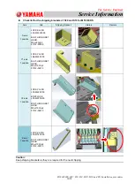
Make sure that all the requirements for installing the machine have been delivered to the 
installation site. 

If the requirements for installing the machine have not been delivered to the installation site, inform the 
transport company immediately and have them to ship the items by other truck. 


Check the external temperature. 

If the external temperature is low, condensation may occur. Explain this to the customer and ask them 
to prepare the place to temporarily locate the machine (the difference between the external 
temperature and the temperature in the installation site must be 10 degrees C or less). 
Rent a stove, etc., and gradually warm up the machine. Carry in the machine after confirming that the 
base of the machine temperature rises 5 degrees C.   

Caution: 

Condensation may occur on the machine when the difference between the external temperature and the base of 
the machine temperature is 

10 degrees C or more

.   


Make arrangement with the customer regarding the installation of the machine beforehand. 

Make final checks if the installation of the machine, the electric work and the work for air supply are 
going to be 

performed as scheduled

, and the 

safety precautions 

(as the regulations vary depending 

on the customer). 

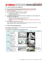
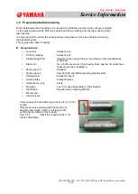
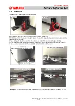
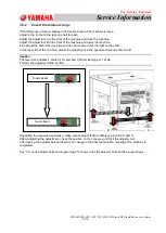
3.2  Unload the machines and equipment 

Normally a transport company unloads the machine from a truck using a forklift, etc. 
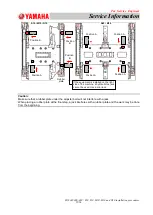
Caution: 

When the machine is on a truck, confirm that the supporting legs (locating in the bottom center of S20 and M20) 
are raised. 

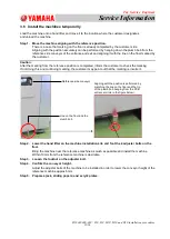
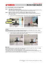
Carry in the machine that was unloaded from a truck to the installation site by operating a transport 
equipment such as a hand lifter, etc. Make sure to follow the precautions below. 


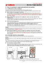
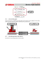
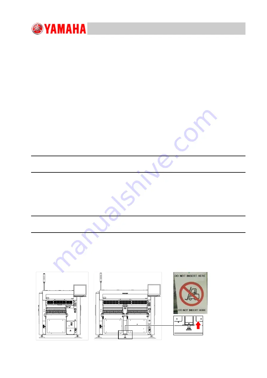
Precaution when operating a forklift 

When the machine is packed, the notice is labelled as shown in the figure below to avoid the fork of the 
forklift and the cover of the machine from interfering with each other. 
Do not insert the fork into the labelled part as the cover, etc., may be damaged. 
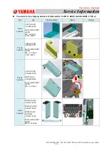
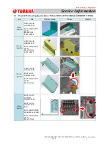
 

See 

“5.1 

Unload the machine by suspending

 for unloading the machine operating a unic. 

S10, M10 

S20, M20 

Summary of Contents for D10

Page 1: ... the current view of YAMAHA on the issues discussed as of the date of issuance As YAMAHA must respond to changing market conditions it should not be interpreted to be a commitment on the part of YAMAHA and YAMAHA cannot guarantee the accuracy of any information presented after the date of issuance This document is provided for information purposes only and it is provided without any warranties eit...

Page 2: ... Correction and adjustment of levelness 18 3 8 1 Check the X beam torsion 18 3 8 2 Case if the torsion is large 19 3 9 Lock adjuster bolts and support legs 20 4 Setup after installing the machine 22 4 1 Install accessories 22 4 2 Install the LCD monitor and the balancer 22 4 2 1 Previous LCD monitor 22 4 2 2 Current LCD monitor 23 4 3 Air and power connection 24 4 3 1 Connect the air and power to ...

Page 3: ...cable conductor cross section 3 5mm2 or more Leakage current 20mA or less Installation environment requirement Item Detail Remark Noise Meeting EN61000 6 2 standard Humidity 50 60 non condensing Temperature Operation assurance Within the range from 10 to 35 degrees C Accuracy assurance 23 2 degrees C The average over a period of 24 hours does not exceed 30 degrees C Altitude 1 000m or below above ...

Page 4: ...r source and the air supply Make sure that the customer is informed of the specified capacity of the power source for the machine Make sure that the customer is informed of the specified diameter of the air pipe and its airflow Make sure that the schedule for the electric works and the air piping works are set according to the installation schedule as required Weather and temperature on the day of...

Page 5: ...he installation site must be 10 degrees C or less Rent a stove etc and gradually warm up the machine Carry in the machine after confirming that the base of the machine temperature rises 5 degrees C Caution Condensation may occur on the machine when the difference between the external temperature and the base of the machine temperature is 10 degrees C or more Make arrangement with the customer rega...

Page 6: ...problem later on Take some pictures of the damage Make sure to get the customer s permission before doing so Remove plastic wrapping from the machine After moving the machine to near the production line or the entrance of the clean room remove the plastic wrappings from the machine and the accessories 3 4 Remove the shipping brackets See Checklist for the shipping brackets for the procedure of rem...

Page 7: ...tus Remark X axis 1 position LOCK X AXIS LF1 M220Y 00 BOLT HEX SOKET HEAD M4 L8 Qty 4 91312 04008 Y1 axis 1 position LOCK Y AXIS LE6 M260Y 00 BOLT HEX SOKET HEAD M5 L10 Qty 2 91312 05010 Y2 axis 1 position LOCK Y AXIS LF3 M220Y 00 BRKT LOCK LF3 M220X 00 BOLT HEX SOKET HEAD M5 L10 Qty 4 Z axis 1 position BRKT Z AXIS L LF3 M7193 00 BRKT Z AXIS R LF3 M7192 00 BRKT Z AXIS BOTTOM LF3 M7191 00 BOLT HEX ...

Page 8: ...mark X axis 1 position LOCK X AXIS LF1 M220Y 00 BOLT HEX SOKET HEAD M4xL8 Qty 4 91312 04008 Y1 axis 1 position LOCK Y AXIS LE6 M260Y 00 BOLT HEX SOKET HEAD M5xL10 Qty 2 91312 05010 Y2 axis 1 position LOCK Y AXIS LF3 M220Y 00 BRKT LOCK LF3 M220X 00 BOLT HEX SOKET HEAD M5xL10 Qty 4 Z axis 1 position BRKT Z AXIS BOTTOM LF3 M7191 00 BRKT Z AXIS LF3 M7192 01 Qty 2 BOLT HEX SOCKET HEAD M2 5xL6 Qty 4 BOL...

Page 9: ...mark X axis 1 position LOCK X AXIS LF1 M220Y 00 BOLT HEX SOKET HEAD M4xL8 Qty 4 91312 04008 Y1 axis 1 position LOCK Y AXIS LE6 M260Y 00 BOLT HEX SOKET HEAD M5xL10 Qty 2 91312 05010 Y2 axis 1 position LOCK Y AXIS LF3 M220Y 00 BRKT LOCK LF3 M220X 00 BOLT HEX SOKET HEAD M5xL10 Qty 4 Z axis 1 position BRKT Z AXIS BOTTOM LF3 M7191 10 BRKT Z AXIS LF3 M7192 01 Qty 2 BOLT HEX SOCKET HEAD M2 5xL6 Qty 4 BOL...

Page 10: ... LOCK X AXIS LF3 M220W 00 BOLT HEX SOKET HEAD M5xL8 Qty 2 91312 05008 Y1 axis 1 position LOCK Y AXIS LE6 M260Y 00 BOLT HEX SOKET HEAD M5xL10 Qty 2 91312 05010 Y2 axis 1 position LOCK Y AXIS LF3 M220Y 00 BRKT LOCK LF3 M220X 00 BOLT HEX SOKET HEAD M5xL10 Qty 4 91312 05010 Z axis 1 position LOCK Z AXIS LF3 M740Y 00 BOLT HEX SOKET HEAD M5xL10 Qty 2 91312 05010 Caution Keep shipping brackets as they ar...

Page 11: ...least 2 pcs Dedicated jig PCB Required when connecting our machine to other manufacturer machines Steel ruler 1m or 60cm steel ruler If not having them approx 3m metal tape measure can be substitution 46mm wrench At least 2 30mm wrench Used for S20 and M20 supporting adjuster bolts Sliding paper At least 8 sheets Acrylic plates At least 8 plates Hydraulic toe jack 4 sets Mini jack 1 set it is used...

Page 12: ...pleted inform the customer to check the marking If not doing this and continuing marking the customer may point out that the marking is incorrect Step 2 Lower the hand lifter on the machine installation site and foot the 4 adjuster bolts on the floor Bring the machine near the reference machine as much as possible and install the machine Within 10mm from the reference machine is desirable Step 3 L...

Page 13: ...nd level the X and Y directions temporarily Check if the positions to place the level vial are clean and there is no foreign object on the surface If it is contaminated clean it with waste cloth If there are two level vials use one for checking the levelness in the Y direction and use the other for the X direction and place them in the machine How to level the machine Adjust the height of the adju...

Page 14: ...ne the fine adjustment of the machine position and the leveling can be performed effectively using a hydraulic jack 3 7 3 Jack setting positions of the machine See below for the jack setting positions of each machine Hydraulic toe jack toe load capacity 2tons Mini jack load capacity 5 tons Acrylic plate Sliding papers Qty 2 Acrylic plate Low High Low Low Low High High High Target Target Acceptable...

Page 15: ...nterfere with a jack When placing a rubber plate at the final step a jack interferes with a rubber plate and the work may be done from the beginning S20 M20 S10 M10 D10 Rubber plate If the equipment is installed on the right side of the machine a hydraulic toe jack cannot be used Use a mini jack Position A Position A Position A Position A Position A Position B Position B Position B ...

Page 16: ... hydraulic toe jack from the outer cover side of the machine at the position B the cover is longer than the frame downward And when setting a wood plate between a jack and the machine frame make sure that the wood plate will not interfere with the cover The stroke of the mini jack is 60mm only Use a wood plate or an aluminum plate for the height raising Rear of a jack setting position Front of a j...

Page 17: ...jack is raised Make sure not to push the machine excessively When pushing the machine push the lower side of the machine Install the machine to the position where the space between machines is less than 5mm If pushing the upper side of the machine it will shake and may not be moved Step 4 Align the transfer height Raise each jack to the same height while confirming the level vial Step 5 Place the ...

Page 18: ...e fine adjustment If turned the adjuster bolt in order to adjust the torsion of X beam it influences the leveling of the machine base Therefore check the position again Caution There is a case that the X beam torsion and the machine leveling may not be compatible In that case prioritize the leveling of the X beam torsion Align the Y axis direction with the reference machine if it is installed The ...

Page 19: ...ount of the right and the left In the rear side of the machine adjust the adjust foots in the opposite directions of A and B Caution The level vial indicates 1 scale for 1meter and 0 02mm leaning per 1 scale Perform the adjustment little by little Regarding the measurement above make sure to adjust that the difference is within 0 02mm After completing the adjustment check the position on the conve...

Page 20: ... the lock nut to tighten 4 adjuster bolts Caution When tightening the lock nut the transfer height rises by the amount of backlash of the screw Approx 0 5mm The specified value of the tightening torque 700N m 2 Tap the part of the adjuster bolts that contact the floor with a wrench or a copper hammer to make sure that they are grounded firmly on the floor Reference Tap several different points on ...

Page 21: ...ake sure that one person checks the pressure intensity of the blots and lock the lock nut to prevent the variation When tightening the lock nut secure the adjuster bolts with a wrench and rotate the lock nut If the contact pressure of the lock nuts in the center is too high the contact pressure of the lock nuts on the outer side decreases which causes the vibration Step 4 Make sure that contact pr...

Page 22: ...rews and the nuts make sure to perform with the posture of Fig B If the weight locates the bottom Fig D the adhesive between GOM and the weight may peel off Balancer unit Monitor bracket Fig A The balancer is attached to the back of the monitor Fig B Balancer unit Fig C Inside of balancer Fig D Status when shipping Fig B Fig A Fig C Fig D When shipping the weight inside of the balancer is adhered ...

Page 23: ...fixing screws The screws are installed to the back of the monitor Use the screws and install the monitor to the monitor bracket BALANCER LE7 M131L 11 GOM LE7 M132M 00 Shockproof rubber 1 Remove the fixing screws 2 Remove the nuts 3 Install the monitor After removing the fixing screws confirm that the balancer is adhered to GOM with the correct posture Nut BRAKT MONITOR LE6 M1312 E1 4mm L14mm Qty 4...

Page 24: ...allation procedures 24 34 4 3 Air and power connection 4 3 1 Connect the air and power to the machine Rod terminal with insulation NICHIFU TMEV TC3 5 11 The equivalent product is also available PE L3 W L2 V L1 U Supply side air coupler 85SN or FBH 85SN Nitto Kohki product or equivalent ...

Page 25: ... the adjustment Step 3 Activate the vacuums of all heads Activate the vacuums of all heads by manual button and check that the measurement value of the manometer is 430Kpa or more If the measurement value is less than 430Kpa adjust the regulator in order the value to be 430Kpa or more Step 4 Stop activating the vacuums of all heads Stop activating all the heads by manual button Measure with the ma...

Page 26: ...each on the conveyors at the connecting part of the reference machine and the adjacent machine and check if the height of the conveyors is the same Adjustment when the transfer is not smooth and there is a gap between the machines Move the machine turn the adjuster bolt and etc and perform the adjustment Note When sliding the board push it against the reference conveyor and then the movable convey...

Page 27: ... by suspending This section describes how to unload the machine by suspending such as using a truck with a unic The figure below is M20 Caution When using the arm make sure that the wires do not interfere with the machine When raising the arm the wires stretch and they come closer to the machine It is safer to protect the machine with a blanket Do not apply shock to the machine when unloading it A...

Page 28: ...sfer height falls within 900 10mm in the whole production line as shown in the figure below and the reference machine is installed on the left end adjust the machine height so that the board transfer height is to be approx 910mm When the levelness of the floor falls within the specification 900 10mm When the levelness of the floor does not fall within the specification 900 10mm Caution When a mach...

Page 29: ...site is not made of concrete reinforce the position on the floor where the legs of the machine are placed Consult with the experts who are familiar with the installation site When using the feeder exchange carriages When setting the feeder exchange carriage to the front and to the rear side of the machine the flatness of the floor including the space under the machine should fall within 10mm The f...

Page 30: ...rical contact Defect in the electrical system e g Short circuit on the circuit board or at the connection part due to penetration of the water Caution If the machine is connected to the power source with the condensation on the body the electric portion breaks NEVER TURN ON the machine until it is confirmed that no condensation is on the machine 5 3 1 The formation process of condensation on the m...

Page 31: ...the machine is almost the same as the outside air temperature after being exposed to the open air Outside air temperature 10 deg C Indoor temperature 20 deg C Humidity 60 Temperature of the machine 10 deg C Cold mounter 10deg C Indoor temperature 20 deg C Humidity 60 The dew condensation occurs due to the air whose temperature has dropped below 12 deg C The air is chilled by the cold surface of th...

Page 32: ...se the air conditioner to warm up inside the vehicle while transporting the machine to prevent the machine gets cooled down before being carried into the installation site 5 3 3 When condensation occurs Take the machine out of the room After performing the following carry the machine into the room again Agitate the air around the machine by fanning with an electric fan Warm up the machine Use a dr...

Page 33: ...r between the mounter and the wrap to warm up the mounter and the air inside the wrap In this way the mounter can be warmed up effectively If the machine is covered with the plastic wrap the condensation occurs on the outer surface of the wrap and the drier is not required After a while cut the plastic wrap with scissors and unwrap it from the top Wrap the plastic wrap around the machine from bott...

Page 34: ...ngineer Service Information SI1604009E 002 S20 S10 M20 M10 and D10 installation procedures 34 34 6 Revision history No Contents Note Date 000 First release June 14 2016 001 Addition of head fixing jig April 12 2017 ...

Reviews: