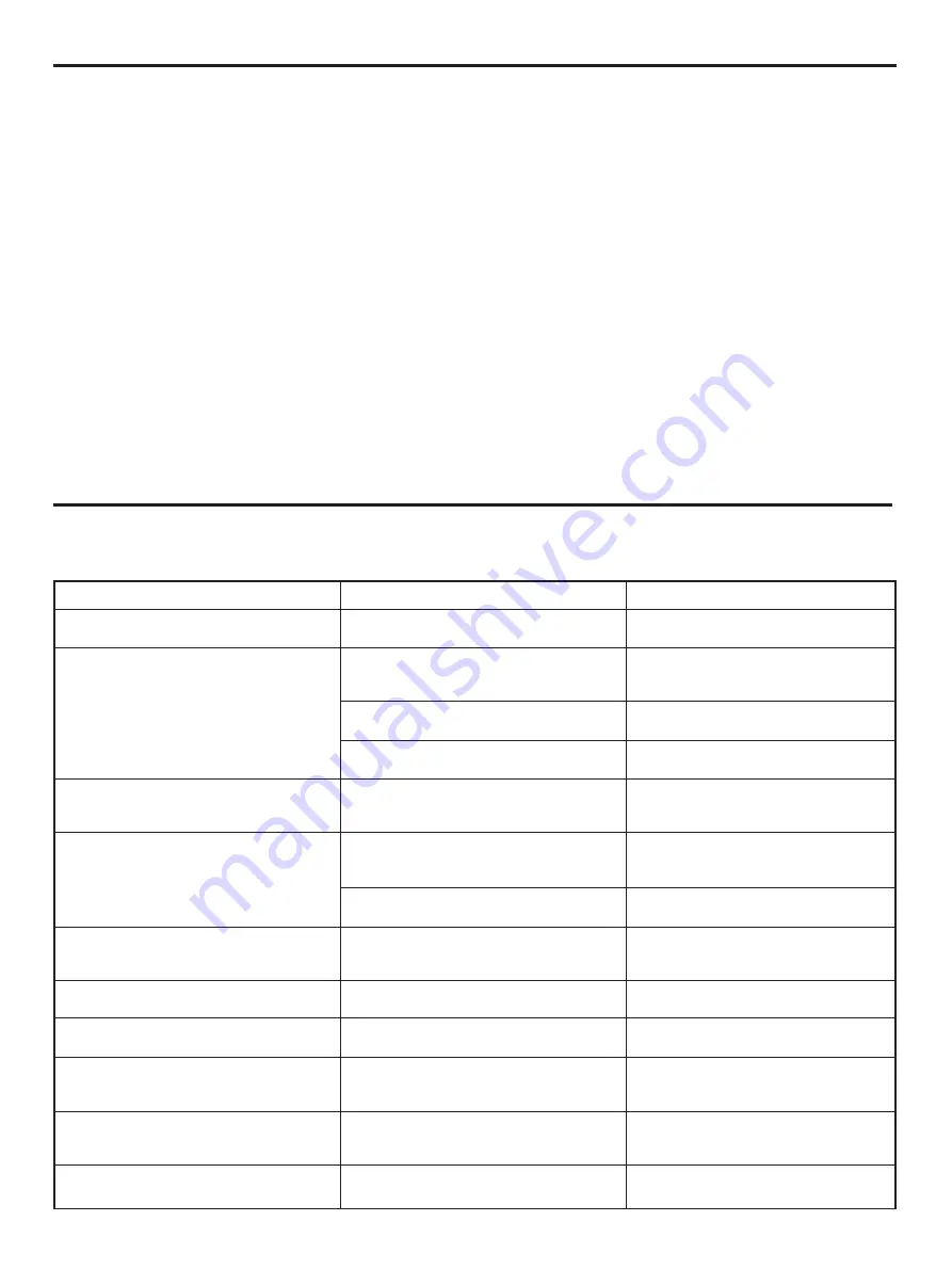
background image

18

SYMPTOM

The unit fails to turn on when the
POWER switch is pressed.

No sound.

Sound “hums”.

Poor bass reproduction.

Sound output level to either or both
of the rear surround speakers is
lower than other speakers.

No sound from the center speaker.

No output of LFE sound.

Whole sound level is low, even
though the volume is increased on
the amplifier.

The difference of sound level
between a high level part and a low
level part is too great.

Noise from nearby TV or tuner.

CAUSE

Power cord is not plugged in or is not
completely inserted.

Incorrect input or output cord
connections.

Improper input mode selection.

Improper input mode selection on the
amplifier.

Incorrect cord connections.

The setting of LFE/BASS OUT is at the
SUBWOOFER position, though your
system does not include a subwoofer.

Output mode selection for each channel
(MAIN, CENTER or REAR) is improper.

Sound output level to either or both of
the rear surround speakers is
decreased.

The setting of CENTER SP. is at the
PHANTOM position.

The output level of LFE (LFE MIX LVL)
is adjusted to MUTE.

Output level (OUTPUT TRIM)
adjustment on this unit is low.

The setting of the DYNAMIC RANGE is
at the MAX position.

This unit is too close to the affected
equipment.

REMEDY

Firmly plug in the power cord.

Connect the cords properly.  If the
problem persists, the cords may be
defective.

Select the proper input mode (RF, OPT
or COAX).

Select the “5-ch discrete AC-3 input”
mode on the amplifier.

Firmly connect the audio plugs. If the
problem persists, the cords may be
defective.

Select the MAIN position.

Make output mode selections suitable
for your speaker system.

Increase the level.

Select the SML or LRG position.

Increase the level.

Increase the level.

Select the STANDARD position.

Move this unit further away from the
affected equipment.

If the unit fails to operate normally, check the following points to determine whether the fault can be corrected by the simple
measures suggested.  If it cannot be corrected, or if the fault is not listed in the SYMPTOM column, disconnect the power cord and
contact your authorized YAMAHA dealer or service center for help.

TROUBLESHOOTING

SPECIFICATIONS

Output Level/Output Impedance

MAIN L/R, CENTER, SURROUND L/R

1 kHz, 0 dB INPUT...............................................2V/1.2 k

SUBWOOFER

50 Hz, 0 dB INPUT...............................................6V/1.2 k

Input Impedance (RF, COAXIAL).........................................75

Frequency Response

MAIN L/R, CENTER, SURROUND L/R (LARGE)

20 Hz–20 kHz..........................................................0

5

1 dB

Filter Characteristics

MAIN L/R, CENTER, SURROUND L/R (SMALL)

H.P.F. ..................................................fc=90 Hz, 12 dB/oct.

SUBWOOFER

L.P.F. ...................................................fc=90 Hz, 24 dB/oct.

Total Harmonic Distortion

MAIN L/R, CENTER, SURROUND L/R (1 kHz)

...........................................................................0.01% or less

SUBWOOFER (50 Hz) ......................................0.01% or less

Signal to Noise Ratio (IHF-A).............................105 dB or more

Channel Separation (1 kHz).................................80 dB or more

Power Supply

U.S.A. model..................................................AC 120V, 60 Hz
General model .....................AC 110/120/220/240V, 50/60 Hz

Power Consumption ............................................................35W

AC OUTLET

UNSWITCHED x 1 ................................................200W max.

Dimensions (W x H x D) ............435 mm x 126 mm x 351.7 mm

(17-1/8” x 4-15/16” x 13-7/8”)

Weight ........................................................6.1 kg (13 lbs. 7 oz.)

* Please note that all specifications are subject to change

without notice.

Summary of Contents for DDP-1

Page 1: ...Off the Power of This Unit 8 Table of Functions 9 Adjustments Before Operation 10 Playing an AC 3 Source 14 Adjusting Output Levels 14 Adjusting Delays and Dynamic Range 16 Specifications 18 Troubleshooting 18 Block Diagram 19 OWNER S MANUAL IMPORTANT Please record the serial number of this unit in the space below Serial No The serial number is located on the rear of the unit Retain this Owner s M...

Page 2: ...ce receptacles and the point where they exit from the unit 12 Cleaning The unit should be cleaned only as recommended by the manufacturer 13 Nonuse Periods The power cord of the unit should be unplugged from the outlet when left unused for a long period of time 14 Object and Liquid Entry Care should be taken so that objects do not fall into and liquids are not spilled into the inside of the unit 1...

Page 3: ...ments apply ONLY to those products distributed by Yamaha Corporation of America or its subsidiaries FCC INFORMATION for US customers only YAMAHA and the Electronic Industries Association s Consumer Electronics Group want you to get the most out of your equipment by playing it at a safe level One that lets the sound come through loud and clear without annoying blaring or distortion and most importa...

Page 4: ...ound processing format developed for 35 mm film movies by employing a new kind of low bit rate audio coding Dolby Surround AC 3 is a digital surround sound system that provides completely independent multi channel audio to consumers In multi channel form Dolby Surround AC 3 provides five full range channels in what is sometimes referred to as a 3 2 configuration three front channels left center an...

Page 5: ...t of your system Surround speakers and a center speaker do not have to be equal to the main speakers For precise sound localization however it is ideal to use high performance models that can reproduce sounds in full range If for some reason it is not practical to use a center speaker you can enjoy AC 3 effect without it Best results however are obtained with the full system Main In normal positio...

Page 6: ... switch OFF the power to this unit and to any other components to which connections are being made When making connections between this unit and other components be sure all connections are made correctly L left to L R right to R Also refer to the owner s manual for each component to be connected to this unit AC 3 RF OUT INPUT OUTPUT OPTICAL COAXIAL AC 3 DIGITAL AC 3 RF MAIN CENTER SURROUND SUBWOO...

Page 7: ...to protect the terminal from dust AC OUTLET UNSWITCHED The power cord of any audio video unit can be connected to this outlet The power to this outlet is not controlled by this unit s POWER switch This outlet will supply power to the connected unit even if this unit is turned off The maximum power that can be connected to this outlet is 200 watts OPTICAL COAXIAL AC 3 DIGITAL I20V 60Hz I 6A MAX 200...

Page 8: ...wer of this unit when you will play an AC 3 source an AC 3 laserdisc etc or if you desire to make some adjustments or mode setting changes to this unit YA M A H A AC 3 DECODER AC 3 DECODING f s 4 8 k c h 3 2 N O AC 3 DATA I N P U T R F Sampling frequencies Audio code 3 Three channel outputs at the front left main center and right main 2 Two channel outputs at the front left main and right main 1 C...

Page 9: ... COAXIAL RF 2 CENTER SPEAKER SMALL LARGE PHANTOM SMALL 3 REAR SPEAKERS SMALL LARGE SMALL 4 MAIN SPEAKERS SMALL LARGE LARGE 5 LFE BASS OUT MAIN SUBWOOFER MAIN The following 15 functions on this unit allows you to change several adjustments and mode settings for enhancing the performance of your audio system including this unit For adjustment or mode setting change on each menu function refer to pag...

Page 10: ...ow 90 Hz at the main channels are output from the SUBWOOFER OUTPUT terminals if the SUBWOOFER position is selected on C5 LFE BASS OUT LARGE Be sure to select this position if this unit is connected to an amplifier or receiver RX V2090 etc equipped with 5 ch discrete AC 3 input terminals In this position full range signals present at the main channels are output from the MAIN OUTPUT terminals Selec...

Page 11: ... appears on the display 4 Press side or side once or more so that the arrow points the position you will select 5 Repeat step 3 and 4 to change selections on other functions in the same way Note If there is no operation for about 5 seconds the original message will be restored on the display MODE MENU PARAMETER Method of changing selections 1 2 3 4 C1 INPU RF O C1 INPUT RF OPT COAX C1 INPUT RF OPT...

Page 12: ...he following message appears on the display 4 Press side once so that the arrow points ON 5 Turn up the volume on the amplifier You will hear a test tone like pink noise from the left main speaker then the center speaker then the right main speaker then the right surround speaker and then the left surround speaker for about two seconds each The display changes as shown below 12 MODE MENU PARAMETER...

Page 13: ...st tone from the right surround speaker to be at the same level as other speakers Pressing increases and decreases the value Pressing and holding the button will change the value continuously 10 When the adjustments are finished Press once or more until the following message appears on the display 11 The test tone will stop 13 PARAMETER MENU PARAMETER MENU PARAMETER MENU MODE TEST 7 9 11 1 6 8 10 ...

Page 14: ...D LEVEL B4 LFE MIX LEVEL B5 OUTPUT TRIM Description of each function B2 LEFT SURROUND LEVEL Control range 6 dB to 6 dB in 1 dB step Preset value 0 dB Adjusts the output level at the left surround channel You had already adjusted the level in OUTPUT BALANCE ADJUSTMENT on page 13 however you can change the level if you wish B3 RIGHT SURROUND LEVEL Control range 6 dB to 6 dB in 1 dB step Preset value...

Page 15: ...ses and decreases the value Pressing and holding the button will change the value continuously 4 Repeat step 2 and 3 to adjust levels on other functions in the same way Note If there is no operation for about 5 seconds the original message will be restored on the display MODE MENU PARAMETER Method of adjusting levels PARAMETER MENU MODE TEST 1 2 3 B 1 TEST B 2 L E F T S U R L V L 0 d B L V L 0 d B...

Page 16: ...source in a high output level in a room specially soundproofed for audio video enjoyment STANDARD Powerful sounds of extremely wide dynamic range are not always suitable for home use Depending upon the condition of your listening environment it may not possible to increase the sound output level as high as a movie theater however in a level proper for listening to in your room the low level parts ...

Page 17: ...e pressing increases and decreases the value Pressing and holding the button will change the value continuously 4 Repeat step 2 and 3 to make changes on other functions in the same way Note If there is no operation for about 5 seconds the original message will be restored on the display MODE MENU PARAMETER Method of changing the level or the selection PARAMETER MENU MODE TEST 1 2 3 A 1 CE N T A 1 ...

Page 18: ... discrete AC 3 input mode on the amplifier Firmly connect the audio plugs If the problem persists the cords may be defective Select the MAIN position Make output mode selections suitable for your speaker system Increase the level Select the SML or LRG position Increase the level Increase the level Select the STANDARD position Move this unit further away from the affected equipment If the unit fail...

Page 19: ... HPF HPF HPF LPF 4th order LPF 4th order 2nd order 2nd order 2nd order 2nd order 2nd order 20bit D A C4 MAIN SPEAKERS C2 CENTER SPEAKER C3 REAR SPEAKERS C5 LFE BASS OUT 20bit D A CROSSOVER 90Hz MAIN L MAIN R CENTER SURROUND L SURROUND R DDP 1 BLOCK DIAGRAM SUBWOOFER RS LFE LS C L R SUBWOOFER MAIN 20bit D A C1 INPUT B5 OUTPUT TRIM B2 LEFT SUR LEVEL B3 RIGHT SUR LEVEL ...

Page 20: ...shows what terminal s the signals of each channel are output to according to the output mode settings on C2 to C5 See page 10 for details 1 When C5 LFE BASS OUT is set at the MAIN position 2 When C5 LFE BASS OUT is set at the SUBWOOFER position 3 When C2 CENTER is set at the SMALL position 4 When C3 REAR is set at the SMALL position 5 When C4 MAIN is set at the SMALL position The shaded areas show...

Reviews: