background image

Follow the procedure outlined below to install the DME Designer application and the 
DME-N Network Driver using the DME Designer Combo Installer.

02

1-1.


Install DME Designer and DME-N Network Driver  

1-1-1.

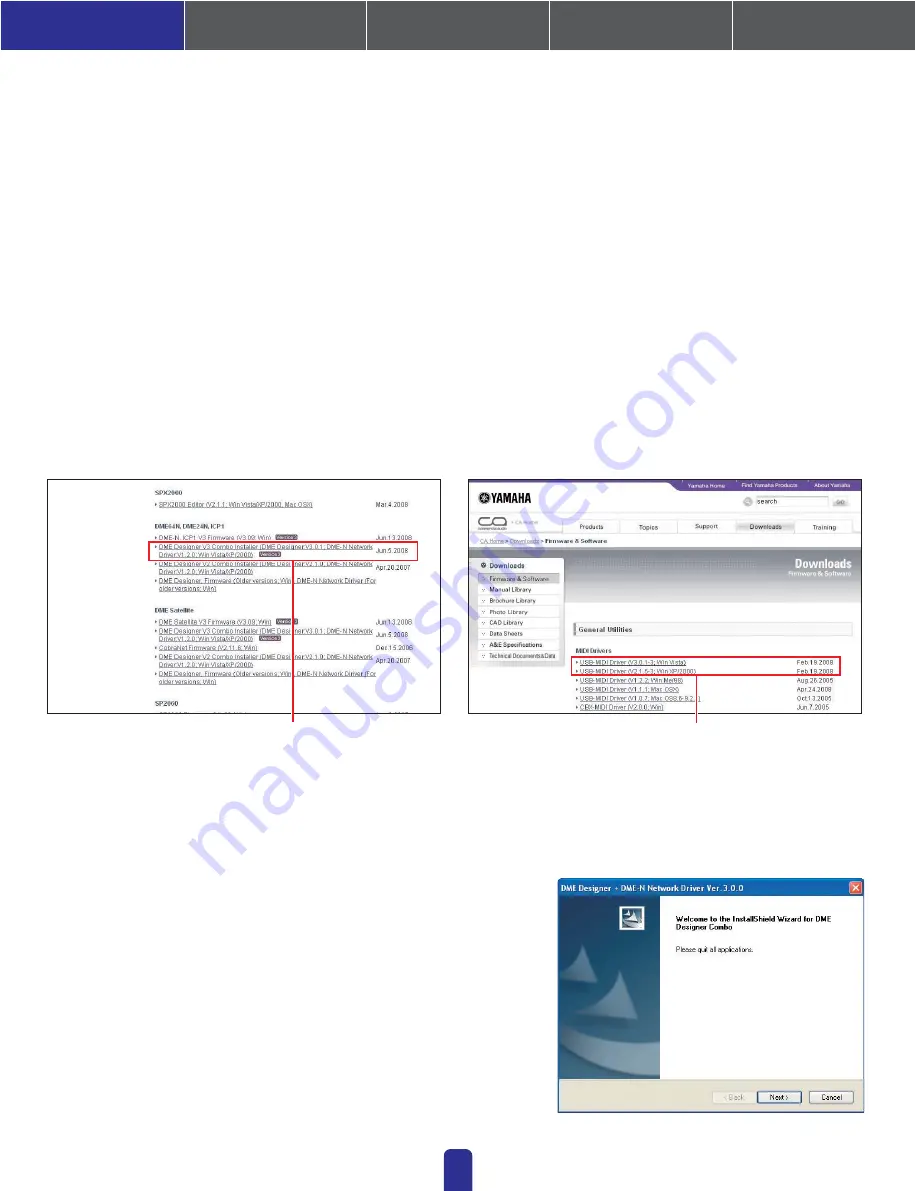
 Once downloaded and extracted, open the DME Designer Combo Installer V*.*.* 

folder and  double-click the “setup.exe” application. 

The setup wizard for the DME Designer Combo Installer will be displayed. (Note: V*.*.* 
indicates the version number of the actual file.)

1-1-2.

 Follow the instructions provided on-screen to install the software. 

DME Designer will be installed first of all, followed by the DME-N Network Driver. During 
this process, the software will be installed inside a folder named “DME Designer” in the 
Program Files\YAMAHA\OPT Tools directory (default).

Note: 

If a previous version of either of these exists on your computer, it will be uninstalled before installation of the 

new version begins. In such a case, you will be asked to restart your computer after the older software has been 
uninstalled. Whether replacing a previous version or installing for the first time, it will be necessary to restart your 
computer. Please follow the instructions given at that time. 

Begin by downloading the DME Designer Combo Installer and the USB-MIDI Driver from the 
“Downloads” page on the Yamaha Pro Audio website 
(http://www.yamahaproaudio.com/downloads/firm_soft/index.html).

Use this link to download the required driver.

Select the correct driver for your computer's OS. 

Note: 

DME Designer V3 supports Windows 2000, XP, and Vista. 

The following items must be downloaded in order that DME Series devices can be connected to a computer and put to practical use. 


DME Designer Combo Installer

Note: 

While it may be downloaded separately, DME-N Network Driver can also be found within the same folder as DME Designer when that application has been downloaded.

1. 

DME Designer: 

This dedicated application is used to make system settings within DME units and to conveniently setup sound-processing configurations.

Note: 

DME Designer can be freely used on your computer even when no DME units are connected.

2.

 DME-N Network Driver: 

This driver is needed in order for your computer and DME unit(s) to be connected via Ethernet.


USB-MIDI Driver: 

This driver is needed in order for your computer and a DME unit to be connected using a USB cable.

When each has been downloaded, please expand it and place the expanded folder in an easy-to-find location such as your desktop. 
Then, follow the steps described below in order to install the software.

1. Installing the Software

4. In-depth information

on DME Units

3. Advanced Setup

(via Ethernet cables)

2. Basic Setup

(via USB cable)

Appendix: Detailed

DME-N Network Driver Settings

DME Designer Combo Installer
(that contains DME Designer application and DME-N Network Driver)

USB-MIDI Driver

1. Installing the Software

Summary of Contents for DME Series

Page 1: ...als This section serves as a guide to online information on Speaker Processor Components library data optional cards and touch panel controllers AMX Creston page 13 Connecting to External Devices This section covers connection to remote controllers via Ethernet or GPI page 16 Troubleshooting Tips Chart This chart serves as a quick guide to the steps that should be taken to ensure correct operation...

Page 2: ... yamahaproaudio com downloads firm_soft index html Use this link to download the required driver Select the correct driver for your computer s OS Note DME Designer V3 supports Windows 2000 XP and Vista The following items must be downloaded in order that DME Series devices can be connected to a computer and put to practical use DME Designer Combo Installer Note While it may be downloaded separatel...

Page 3: ...USB ports The procedure and screen which were described here are a case of WindowsVista When Windows 2000 or Windows XP is used please set up similarly according to directions of a screen For the latest information about DME Designer System Requirements visit the Yamaha Pro Audio website http www yamahaproaudio com 1 Installing the Software 4 In depth information on DME Units 3 Advanced Setup via ...

Page 4: ...ed DME unit for editing double click DME at the left of the Designer window 04 This section covers the most basic configuration that is using a single PC to control a single DME unit 2 Basic Setup Connecting a single DME unit directly to a computer via USB cable Designer window Next either double click the currently connected DME unit a DME24N in this case or drag and drop it to the editing area l...

Page 5: ...hown below and click the OK button 05 Right click Drag and drop the components that you require into the configuration area from the list on the left hand side To connect components click the required input or output port and drag the end of the connecting wire to the required destination When you have setup all connections in the same way as shown below its time to write the configuration to the ...

Page 6: ...e Yes button When writing has been completed the message Saving the Designer file after synchronization will enhance the speed of the next synchronization Do you want to save now will be displayed If you want to save the file click the Yes button After returning to the Synchronization window click the Close button When synchronization has been successfully achieved the On line button at the bottom...

Page 7: ...cause 4 and corrective action The number of registered MIDI devices exceeds the Windows limit The Windows operating system allows a maximum of 10 MIDI device drivers to be installed and registered In certain cases connecting a device to a different USB port can lead to it being recognized as a different device thereby artificially exceeding the limit If MIDI does not function properly therefore tr...

Page 8: ...connection via USB or the use of a commercially available Ethernet USB interface Note A Group Master device must be set for the device group with all other devices in the group set as slaves Furthermore if the DME network contains one or more DME satellites it is recommended that one of the DME satellites be set as the Group Master Note Each DME unit to be networked must be assigned an IP address ...

Page 9: ...se Cat 5 shielded twisted pair cables in order to maximize resistance to electromagnetic interference Note Select Slave in the Master Slave area of the Network Setup window for both the DME8o C and the DME64N Select 100Base TX in the Link Mode area of the Network Setup window for both the DME8o C and the DME64N Setup ports as shown below Select Network Setup from the Hardware menu on the Main Pane...

Page 10: ...d DME N Network Driver Settings 10 3 4 Setting the DME N Network Driver Select Additional Options from the Control Panel 3 3 Connecting DME units to the network switch When the required settings have been made connect all DME units and the computer to the switch using Ethernet cables At this point the network should be setup in the same way as shown in the Device Group diagram on page 08 Select Ad...

Page 11: ...from the Main Panel window Click Select IP Address ensure that the IP addresses for all devices are displayed and then click the Go On Line button When the Sync Direction window is displayed ensure that DME Designer Device is selected and then click the OK button Click the Port button Once a configuration has been setup create at least one scene NOTE If multiple device groups have been set up use ...

Page 12: ...n can take at least twice as long as usual Furthermore if your original project file is accidentally deleted or lost synchronization with DME devices will no longer be possible For safety s sake therefore it is advisable that a backup be made and that the Store Project File into DME after synchronization item from the Synchronization window or the DME File Storage item from the File menu be used t...

Page 13: ...only one DME unit Master is used the IP address should be set to 192 168 0 2 2 The subnet mask is fixed at 255 255 255 0 3 The host address can be set between 2 and 253 for the master device and between 3 and 253 for slaves 4 Unless it is absolutely necessary to use a global IP address you should always use a private address that is 192 168 0 2 through 192 168 255 253 Consult with your network adm...

Page 14: ...eld Device IP Address The IP address of the unit currently selected in the Target Device List can be confirmed and set using these four fields Refer to page 7 for details regarding the confirmation and setting of IP addresses Note Communication with DME units is only possible if the corresponding IP addresses have been correctly setup Device MAC Address These fields display the MAC Media Access Co...

Page 15: ...l button Click Cancel to close the window without making any changes 9 Import Setup from File button When working in a different environment you can import a previously saved setup file To do so click Import Setup from File to display the Open window Then select a setup file and click Open to import the corresponding settings 10 Export Setup to File button You can export setup data to a file for i...

Page 16: ... DME initialization Using the Analyze function Automatic backup function and going online Problem A compile error occurs during synchronization Problem A component or wiring cannot be added Problem A user module is no longer displayed on the list Problem Configurations cannot be switched in the Navigator window Problem A User Module window does not open when the user module is double clicked Probl...

Reviews: