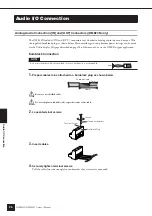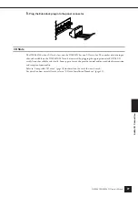
Preparation
Setup Procedure
DME64N/DME24N Owner’s Manual
19
3.
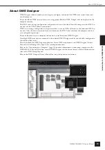
Install the DME Designer software and necessary drivers on the computer to be used for
device group control.
See the “DME Setup Manual” (PDF file) for details.
4.
Connect devices.
• Network connection
Ethernet connection (page 23)
USB connection (page 22)
• Analog connection (page 26)
• External device connection
Remote connection (page 28)
MIDI connection(page 30)
CASCADE connection(page 31)
WORD CLOCK connection(page 32)
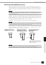
GPI connection (page 33)
5.
Turn power to the computer, DME64N/24N, and related devices on. Press the DME64N/24N
[POWER] switch to turn it on.
To prevent the initial power-on surge from generating a large noise spike or damaging your speaker system, turn
devices on in the following order: audio sources, mixer and/or recorders, and finally power amplifiers. Reverse this
order when turning power off.
No information will appear on the display the first time the device is turned on. The appropriate scene and
other data must first be transferred to the device from the DME Designer.
Refer to the “DME Setup Manual” (PDF file) for details.
Once the appropriate data has been transferred to the device, the current number and name will appear on the
display:
If any scene data has been stored in the DME64N/24N, the current scene and its name will be displayed.
6.
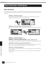
Set up the DME64N/24N operation parameters.
See the “Utility Display” section on page 44 for details.
NOTE
The “NET” page settings must be set up as required before using the unit for the first time.
CAUTION
Summary of Contents for DME64N - Pro Audio
Page 1: ......

