9
DD-55
Upper Case
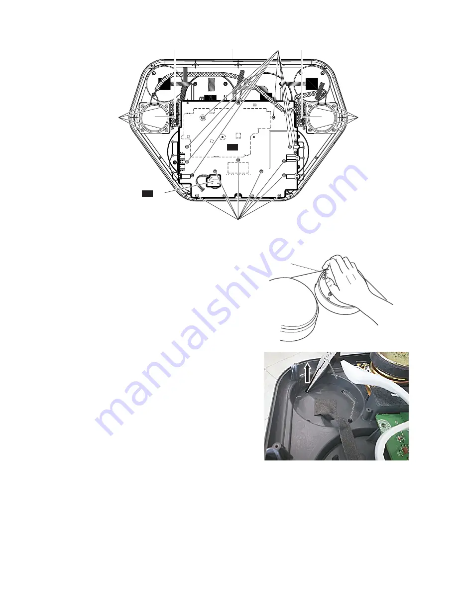
Speaker L
Speaker R
DD
1/2
DD
2/2
[130]
[130]
[135]
[135]
Pad Assembly
(Fig. 7)
(Fig. 6)
[130]: Binding Head Tapping Screw-B 3.0X8 MFZN2Y (EP600250)
[135]: Binding Head Tapping Screw-B 4.0X8 MFZN2Y (EP640410)
Upper Case
Needle-nose plyer
Upper Case
Needle-nose plyer
PAD Assembly
PAD Assembly
Pull up
Pull up
(Fig. 8)
4.
Pad Assembly (Time required: about 5 min)
4-1
Remove the lower case assembly. (See procedure 1.)
4-2
Remove the DD 2/2 circuit board. (See procedure 2.)
4-3
Remove the DD 1/2 circuit board. (See procedure 3.)
4-4
Pull a pad assembly off the panel as shown in the
illustration. (Fig. 7)
*
The pad assembly (S) and pad assembly (L) can
then be removed in the same manner.
5.
Speakers (Time required: about 3 min)
5-1
Remove the lower case assembly. (See procedure 1.)
5-2
Remove the four (4) screws marked [135]. The
speakers can then be removed. (Fig. 6)
*
The left speaker and right speaker can then be
removed in the same manner.
6.
Attaching the Pad Assembly
6-1
Turn over the upper case and support the pad
assembly from the lower side of the case.
6-2
Insert the legs of pad assembly in the holes of the
upper case and then pull them up with a needle-
nose plyer. (Fig.8)
*
All pad assemblies can be attached in the same
way.


