DRX-2
DRX-2
111
(1) analogue CVBS / YC and RGB/YUV
(2) analogue CVBS, YC, RGB/YUV
(3) 2X16Mx16 can be mounted instead of
2x8Mx16 if necessary
SDRAM
2 X 8Mx16
(3)
IDE CONNECTOR
TO/FROM BE AV3
HDD, PCMCIA
BE AV2
UART I2S
I2C
EEPROM
64Kbit
VIP
SAA7118/19
1394
PID1394P25
I2C
EEPROM
64Kbit
OPTIONAL
CHRYSALIS
PNX7100
7400
7703
2FH DENC
OPTIONAL
2FH YUV
VIDEO
1FH VIDEO
OUT
(2)
DIG. AUDIO IN
OPT. & COAX
DIG. AUDIO OUT
I2S AUDIO OUT
I2S AUDIO IN
1FH VIDEO IN
(1)
I2C 0
I2C 0
I2C 1
7004
I2C0
CCIR656
CLOCK
7200
1200
OPTIONAL
OPTIONAL
7201
-5V
FROM POWER SUPPLY
5V
12V
3V3
XIO_1
XIO_0
XIO_0
XIO_0
1394
PID1394L40
1394
CONNECTOR
NORFLASH
4Mx8
NORFLASH
4Mx8
NANDFLASH
8Mx8
7804/7812
Video Part
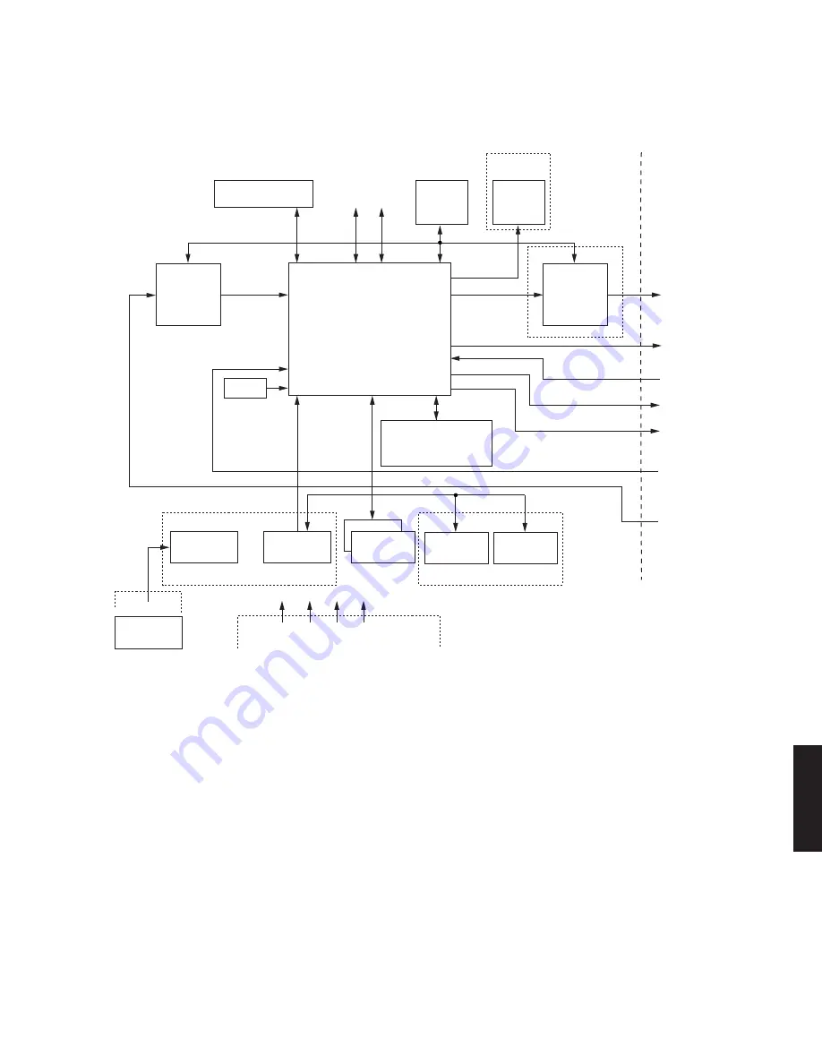
The analogue video input signals CVBS, YC, and YUV/
RGB (RGB for EURO and YUV for USA), are routed via
the analogue board to connector 1904 and sent to IC7004
(SAA7118, Video Input Processor).
The digital video input signals are routed from the DV-In
connector (item 1200) via ICs 7200 (1394 PHY) and 7201
(1394 LINK) to IC7400 (PNX7100, Chrysalis).
The multistandard Video Input Processor (VIP, IC7400)
encodes the analogue video to digital video stream
(CCIR656 format). It provides filtering of the analogue
signals and separation of luminance and chrominance by
a comb filter. The output stream, named ITU_IN(7:0), is
then routed to the Chrysalis IC (PNX7100). This IC
encodes and decodes the digital video stream into/from
MPEG2 format.
5.2 Record Mode
Block diagram Chrysalis Digital Board
Audio Part
I2S audio is sent from the analog board to the Chrysalis IC
via connector 1900. The Chrysalis compresses the I2S
audio data into an MPEG1-L2/AC3 audio stream.
Front-end I2S
IC7400 (Chrysalis) interfaces directly to the DVDR
mechanism (BE) via connectors 1100 (clock and data) and
1105 (control). For future use (with AV3 BE module, HDD,
or card reader) it also interfaces to an IDE bus via
connector 1102 .
It buffers the data streams that are coming from (or going
to) these hardware modules.
In the Chrysalis, the video MPEG2 stream and the audio
AC3 stream are multiplexed into an I2S stream. The serial
data are sent to the DVDR mechanism for recording.
Summary of Contents for DRX-2
Page 105: ...DRX 2 DRX 2 105 3 6 Video routing Video IO Europe ...
Page 109: ...DRX 2 DRX 2 109 4 4 Video routing Video IO NAFTA ...
Page 119: ...DRX 2 DRX 2 119 IC DATA Display Board IC7103 TMP87CH74F ...
Page 120: ...DRX 2 DRX 2 120 IC7103 TMP87CH74F ...
Page 121: ...DRX 2 DRX 2 121 IC7103 TMP87CH74F ...
Page 132: ...DRX 2 132 PRINTED CIRCUIT BOARD FRONT DISPLAY P C B Part 1 Bottom View ...
Page 133: ...DRX 2 133 PRINTED CIRCUIT BOARD FRONT DISPLAY P C B Part 2 Bottom View ...
Page 135: ...DRX 2 135 Part 1 Part 2 PRINTED CIRCUIT BOARD U A models ANALOG P C B Bottom View ...
Page 136: ...DRX 2 136 PRINTED CIRCUIT BOARD U A models ANALOG P C B Part 1 Bottom View ...
Page 137: ...DRX 2 137 PRINTED CIRCUIT BOARD ANALOG P C B Part 2 Bottom View U A models ...
Page 139: ...DRX 2 139 Part 1 Part 2 PRINTED CIRCUIT BOARD G model ANALOG P C B Bottom View ...
Page 140: ...DRX 2 140 PRINTED CIRCUIT BOARD G model ANALOG P C B Part 1 Bottom View ...
Page 141: ...DRX 2 141 PRINTED CIRCUIT BOARD ANALOG P C B Part 2 Bottom View G model ...
Page 190: ...DRX 2 ...


