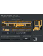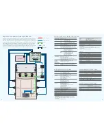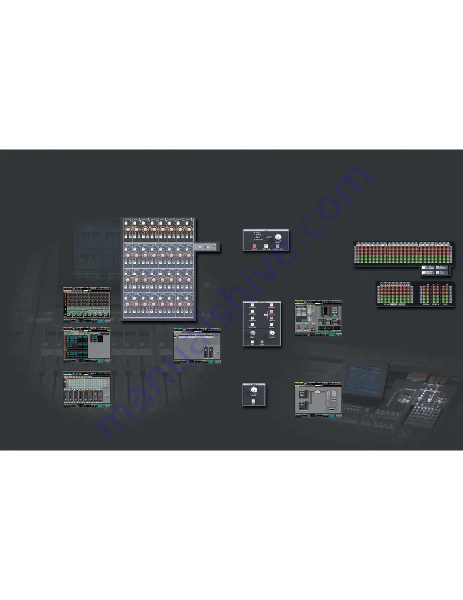
CUE & SOLO
The PM5D V2 provides three cue and solo modes: Mix Cue, Last Cue, and Solo. The PM5D V2
cue system additionally provides four types of cue monitoring: INPUT CUE, DCA CUE,
OUTPUT CUE, and EFFECT or GATE KEY IN CUE with various function settings. There is also a
CUE INTERRUPT function that lets you select whether the MONITOR OUT signal will be
affected by cue/solo operation or not. This last function can be extremely useful in broadcast
applications.
MONITOR
The PM5D V2 MONITOR section offers a range of monitor source selection keys: 2 Track In
Analog 1 and 2, 2 Track In Digital 1 through 3 (all with sample rate converters), STEREO A
and B for the console’s stereo busses (these buttons can be pressed simultaneously to allow
LCR monitoring), and a DEFINE key that can be assigned to select any source. Also USER
DEFINED KEYS can be assigned for this purpose, so you can monitor-select as many sources
as you like at the touch of a button. Individual level controls are provided for the MONITOR
OUT and PHONES outputs.
TALKBACK
In addition to the talkback microphone signal, the PM5D V2 TALKBACK setup display allows
the signals from any one of the AD inputs to be mixed with the microphone signal, and the
TALKBACK destination can be assigned freely to any of the output ports. The TALKBACK ON
button can be set for latched or unlatched operation.
Level Meters
A complete set of level meters is provided on the console panel. Layer select keys let you
monitor any input channel layer plus the stereo inputs or effect returns. The MIX/MATRIX
key allows visual monitoring of the mix buses and matrix outputs. Individual stereo meters
are also provided for the STEREO A, STEREO B, and CUE buses. A PEAK HOLD key engages or
disengages the meter peak hold function. In addition, a comprehensive range of meter
facilities are provided via the LCD display showing all inputs, outputs, input gain reduction
and output gain reduction. Flat meters won’t obstruct the engineer’s view of the stage.
Fl e x i b l e M i x i n g Fo r A ny A p p l i c a t i o n
Co m p r e h e n s i ve M o n i t o r i n g Fa c i l i t i e s
In addition to dual stereo mix buses that can be used together for LCR send, the PM5D V2 offers 24 independent mix buses that
you can use for submix, auxiliary, effect, or just about any other type of send your application requires ... all with master mix control
as well as individual mix send level control from all available inputs. All mix buses have 8-band EQ, compression, and delay that you
can control via the SELECTED CHANNEL controls to optimize your submix signals. And if that isn’t enough, there’s also an 8-output
matrix mix for the mix and stereo buses (also equipped with EQ, compression and delay!) on the PM5D V2, plus an additional 8
matrix buses on each DSP5D unit you use. Once you’ve created all the submixes you need, you can group them, as well as the input
channels, by assigning them to the very versatile DCA faders.
MATRIX/ST ROUTING
MIX to MATRIX VIEW
DCA GROUP ASSIGN (In)
DCA GROUP ASSIGN (Out)
MIX Send/Master Controls
Independent MIX control blocks are provided for the mix buses. When the MIX SEND key is
engaged, the MIX encoders adjust the send level from the selected channel to the
corresponding mix buses. When the MIX MASTER key is engaged the encoders function as
master level controls for the corresponding mix buses. You can still use the channel-strip
encoders to adjust mix send level by using the MIX SEND SELECT keys to specify the
destination mix bus. The MIX blocks also include ON keys to turn the corresponding send on
or off, TO STEREO and TO MTRX LEDs to indicate assignment to the stereo and matrix
busses, PAIR LEDs that indicate paired mix sends, and CUE and SEL keys that assign the
corresponding MIX signal to the SELECTED CHANNEL controls when the MIX MASTER mode
is engaged. When an odd-even numbered pair of mix bus sends is assigned as a stereo pair,
the odd-numbered encoder functions as a pan/balance control while the even-numbered
encoder sets the send level for the pair. The MIX controls can be assigned to DCA groups 7
and 8, so a pair of DCA assignment indicators is also provided.
MATRIX Controls
The MATRIX controls comprise an 8-channel
submix matrix from the mix and stereo buses.
Each matrix module features a level encoder,
ON key, CUE key, and SEL key which assigns
that channel to the SELECTED CHANNEL
controls. Like the MIX bus controls, the
MATRIX controls can be assigned to DCA
groups 7 and 8, so a pair of DCA assignment
indicators is provided. PAIR LEDs indicate
paired matrix controls. When an odd-even
numbered pair of matrix controls is assigned
as a stereo pair, the odd-numbered encoder
functions as a pan/balance control while the
even-numbered encoder sets the send level
for the pair.
DCA Faders
Any input or output channels can be assigned
to any of the console’s eight DCA faders for
convenient grouping. Each DCA strip also
includes a four-character name display as
well as MUTE and CUE keys for convenient
muting and cue monitoring of the
corresponding DCA signal. The faders can
also be used to control individual bands of
the internal graphic equalizers. In fact, you
can assign a variety of functions to the DCA
faders that can be instantly recalled via the FADER MODE keys. You could, for example,
assign input channel level control to the DCA faders so you have simultaneous control of 32
channels instead of the normal 24. Or you could assign mix master levels, matrix levels ...
whatever you need to work in the most productive, efficient manner for the job at hand.
STEREO Faders
The master stereo faders control the output
from the console’s STEREO A and STEREO B
buses. In addition to the faders the STEREO
strips include channel ON keys, TO MTRX and
COMP LEDs, CUE keys, and SEL keys which
assign the corresponding STEREO bus signal
to the SELECTED CHANNEL controls. The
STEREO OUTPUT block also features RECALL
SAFE and MUTE SAFE LEDs similar to those on the input and output channels, and DCA 7 and
8 LEDs that indicate assignment to the corresponding DCA faders. The STEREO B strip
additionally features a MONO key that sums the STEREO B channels to a mono signal that
can serve as the center channel for LCR configurations.
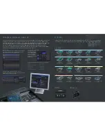
Output Patching
As with input patching, all outputs can be conveniently patched to just about anywhere you
need them via the LCD display screen patch matrix without having to physically re-patch
cables. The mix outputs, stereo outputs, matrix outputs, mono and stereo channel insert and
direct outs, oscillator output, talkback output, and monitor outputs can be patched to the
console’s mix outputs, cascade outputs, option slot outputs, and any of the three 2TR digital
outputs. Send to internal effects can be patched anywhere from the MIX outputs and INSERT
OUT points. Inputs and outputs on connected DSP5D units can be patched directly from the
PM5D V2 in the same way and just as easily as the console’s own inputs and outputs.
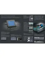
Staying in touch with your sound is vital to create the perfect mix. The PM5D’s in-depth cue, monitor and metering facilities let you
hear what’s happening at any point in the mix with maximum ease and efficiency.
MONITOR
TALKBACK
10
11
Left of LCD
Right of LCD


