PM5DV2/DSP5D Editor Owner’s Manual
24
F
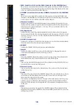
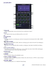
DECAY (Decay time)
Specifies the time over which the gate will close after the hold time has elapsed.
G
ATTACK (Attack time)
Specifies the time from when the key-in signal exceeds the threshold level until the gate opens.
H
HOLD (Hold time)
Specifies the time that the gate will remain open after the key-in signal falls below the threshold.
I
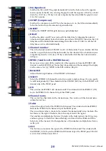
ON (On/off)
This button switches the gate on/off.
J
LIBRARY
This button accesses the gate library. Clicking this button will open the GATE page of the LIBRARY window.
K
LINK (Stereo link)
This button links the parameter settings and key-in signals of adjacent odd-numbered/even-numbered input
channels or the L/R sides of a ST IN channel, so that gating will operate in tandem for the two channels.
L
KEY IN SOURCE
Select the desired key-in signal from the following choices.
M
CUE
This button cue-monitors the currently selected key-in signal.
N
KEY IN FILTER
Select the type of filter applied to the selected key-in signal; HPF (high pass filter), BPF (band pass filter), or LPF
(low pass filter). The ON/OFF button located immediately below switches the filter on/off.
If you’ve selected BPF, use the two knobs at right to adjust the band pass frequency and Q. If you’ve selected HPF
or LPF, use the knob at left to adjust the cutoff frequency.
SELF PRE EQ
The pre-EQ signal of the currently selected input channel
SELF POST EQ
The post-EQ signal of the currently selected input channel
CH 1–48 POST EQ
The post-EQ signal of the corresponding input channel (however, you can only choose
channels belonging to the same group, within the seven groups CH1–8, CH9–16,
CH17–24, CH25–32, CH33–40, CH41–48, and ST IN 1L/1R–4L/4R).
ST IN 1L/1R – 4L/4R POST EQ
MIX 21–24 OUT
The output signal of the corresponding MIX channel immediately before the output
attenuation

