RHH135
4
JK2
CN5
CN5
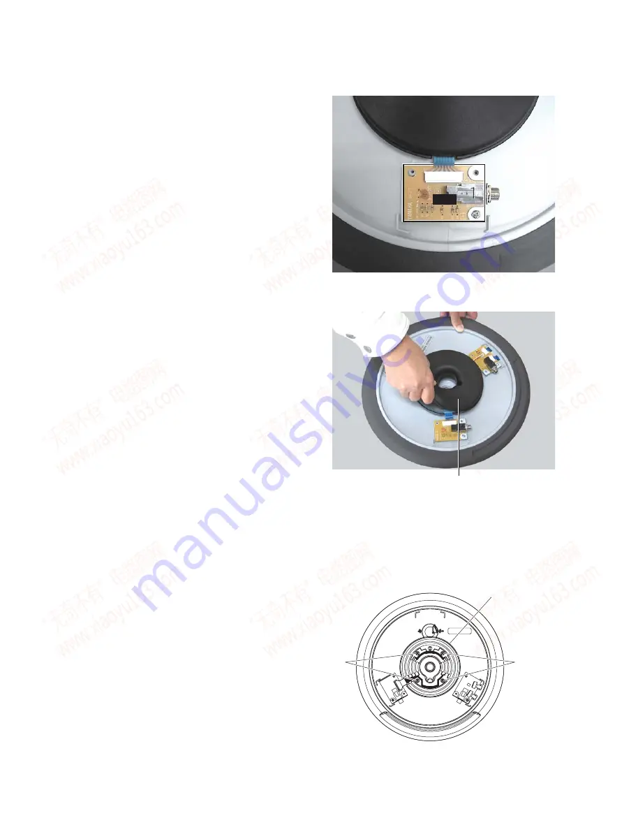
Photo 2
(写真 2)
Photo 3
(写真 3)
Fig.3
(図 3)
[120]: PW Head Tapping Screw-B(Bタイト+PWH)
3.0X12 MFZN2B3 (WM788200)
(RHH アクチュエータ)
RHH actuator
<Bottom view
(底から見た図)
>
[120]
[120]
Sensor board
(センサーボード)
2.
RHH Sheet Switch
(Time required: About 2 minutes)
2-1
Remove the rear cover. (See procedure 1-1)
2-2
Disconnect the connector of the JK2 circuit board.
(Photo 2)
2-3
Remove the RHH actuator. (Photo 3)
Remove the following screws and remove the
sensor board. (Fig. 3)
2.
RHH シートスイッチ
(所要時間:約 2 分)
2-1
2-2
JK2 シートのコネクタを外します。
(写真 2)
2-3
RHH アクチュエータを外します。
(写真 3)
(図 3)
[120]: 4 本
* The appearance of the JK1 circuit board is slightly different
from that in the picture.
※ 写真の JK1 シートは、生産品とは若干異なります。
www. xiaoyu163. com
QQ 376315150
9
9
2
8
9
4
2
9
8
TEL 13942296513
9
9
2
8
9
4
2
9
8
0
5
1
5
1
3
6
7
3
Q
Q
TEL 13942296513 QQ 376315150 892498299
TEL 13942296513 QQ 376315150 892498299


