background image


Setting Up


26


DTX900 Owner’s Manual


Creating a Song by Using a Computer


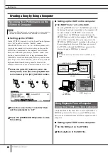
Setting up the DTX900


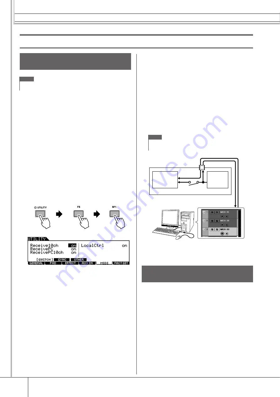
On the DTX900, you need to set the Local Control parame-
ter to “off” in order to avoid a “double” sound. 
When MIDI Thru is set to “on” in a DAW/sequencer soft-
ware on your computer, the note events you play on the 
DTX900 are transmitted to the computer then returned 
back to the DTX900, producing a “double” sound, since 
the tone generator block is receiving performance data 
(MIDI data) from both the keyboard directly and the com-
puter. To prevent such a situation, you need to separate the 
keyboard block from the tone generator block of the 
DTX900. This is why Local Control should be set to “off.” 


1


Press the [UTILITY] button to enter the 
Utility mode, then press the [F5] MIDI but-
ton followed by the [SF1] SWITCH button.


2


Move the cursor to the “LocalCtrl,” then 
set this parameter to “off.”


3


Press the [ENTER/STORE] button to store 
this setting. 


Setting up the DAW on the computer


1


Set MIDI Thru to “on” on the DAW.


By setting MIDI Thru to “on,” the MIDI data generated 
by playing the pad and transmitted to the computer will 
be returned back to the DTX900. As shown in the 
example below, the MIDI data transmitted from the 
DTX900 then recorded to the computer via MIDI chan-
nel 1 will be returned back from the computer to the 
DTX900 via MIDI channel 3 according to the setting of 
the recording track. As a result, the tone generator of 
the DTX900 will sound the MIDI data generated by 
playing the pad as MIDI data of channel 3. 

The instructions below show how to use the DTX900 as a 
MIDI tone generator. In this case, actual MIDI sequence 
data is to be transmitted from a DAW or sequencer on the 
computer. 


Setting up the DAW on the computer


1


Set the MIDI port on the DTX900. 


2


Start playback of the MIDI file. 


Recording Your Performance on the 
DTX900 to Computer


NOTE


• The acronym DAW (digital audio workstation) refers to music software for 

recording, editing and mixing audio and MIDI data, such as Cubase. 


NOTE


• For detailed instructions, refer to the manual of the DAW you are 

using. 


Song Playback From a Computer 
Using the DTX900 as a Tone Generator


USB TO HOST terminal

Tone generator 

block 


(recognizing MIDI


Channel 3 data)


Keyboard 

(output via 

MIDI 

Channel 1)

Local Control = off

IN

CH1

OUT
CH3

Computer

(Cubase, etc.)

MIDI Through = on

DTX900

Summary of Contents for DTX900M

Page 1: ...DTX900 DTX900M EN Owner s Manual...

Page 2: ...s manual carefully and consult your dealer before requesting service ENVIRONMENTAL ISSUES Yamaha strives to produce products that are both user safe and environ mentally friendly We sincerely believe...

Page 3: ...UM TRIGGER MODULE Model Name DTX900 DTX900M This device complies with Part 15 of the FCC Rules Operation is subject to the following two conditions 1 this device may not cause harmful interference and...

Page 4: ...should you forget to turn it off yourself This function automatically turns off the drum trigger module after a set period of inactivity Setting the Auto Power Off function Using the following proced...

Page 5: ...store your work before the drum module turns off If the drum module s AutoPowerOff parameter is set to off this setting will be retained when you import system data that was stored externally regardl...

Page 6: ...owing problems occur immediately turn off the power switch and disconnect the electric plug from the outlet Then have the device inspected by Yamaha service personnel The power cord or plug becomes fr...

Page 7: ...ty of a TV radio stereo equipment mobile phone or other electric devices Otherwise the instrument TV or radio may generate noise Do not expose the instrument to excessive dust or vibrations or extreme...

Page 8: ...but not limited to MIDI data and or audio data is strictly prohibited except for your personal use This product incorporates and bundles computer programs and contents in which Yamaha owns copyrights...

Page 9: ...ated Voice can be assigned to the Drum Kit as desired The instrument is equipped with a Variation Effect which can be used for each Drum Kit as well as Reverb Chorus and Master Effects which can be us...

Page 10: ...6 Re recording a Track After Clearing 48 Assigning a Name to a User Song 49 Using the Groove Check Function 50 Setting the Check Timing 50 Trying Out Groove Check 51 Trying Out Rhythm Gate 52 Saving t...

Page 11: ...ettings F3 EFFECT 127 External Audio Settings F4 AUXIN 128 MIDI Settings F5 MIDI 130 Resetting the User Memory to the Initial Factory Settings F6 FACTSET 131 Chain Mode CHAIN 132 Using a Programmed Ch...

Page 12: ...f Drum Kits and Songs arranged in the order you want page 132 u SONG button Pressing this button enters the Song mode allowing you to play an existing Song or record your drum performance pages 35 and...

Page 13: ...output volume of the stereo mix from the OUTPUT L MONO and R jacks 7 PHONES slider page 31 Adjusts the output volume of the stereo mixed sounds for the PHONES jack This is independent from the MASTER...

Page 14: ...slider set ting the digital jack always outputs audio signals at the maxi mum volume level 1 MIDI IN OUT connectors These jacks are for the transfer of MIDI data to and from exter nal MIDI devices 2 U...

Page 15: ...lays with various functions and parameters To navigate your way through these displays and select a desired function use the F1 F6 buttons and the SF1 SF6 buttons When you select a mode the available...

Page 16: ...he NUM icon appears at the lower right corner of the LCD display When the SF6 NUM but ton is pressed in this status each digit 1 9 0 is assigned to the SF1 SF5 and F1 F5 buttons as shown below allowin...

Page 17: ...thod you may want to use the following method selecting the characters directly from a list Inputting Characters Naming etc Move the cursor to the desired location in the name Select a character at th...

Page 18: ...ctions to the DTX900 s input and output jacks WARNING PCY135 DTX900 PCY155 PCY135 KP125W XP120SD RHH135 XP100T XP100T XP100T Attaching the module stand Attach the included module stand to the DTX900 u...

Page 19: ...XP120T Attaching the module stand Attach the included module stand to the DTX900 using the module stand fastening screws Be sure to use the included screws DTX900 Module stand included Module stand f...

Page 20: ...ce in your setup in the order of MIDI masters controllers MIDI slaves receivers then audio equipment mixers amplifi ers speakers etc Make sure that the power adaptor s cord is not bent at an extreme a...

Page 21: ...AUX IN O1V96 SOLO SOLO ON ON SOLO ON SOLO ON SOLO ON SOLO ON SOLO ON SOLO ON SOLO ON SOLO ON SOLO ON SOLO ON SOLO ON SOLO ON SOLO ON SOLO ON SOLO ON SOLO ON ON PEAK SIGNAL PEAK SIGNAL PEAK SIGNAL PEAK...

Page 22: ...IDI connectors or the USB terminal can be used for MIDI data transmission reception However they cannot be used at the same time Select which connector is used for MIDI data transfer in the Utility mo...

Page 23: ...r prompting you to format the device media If so execute the Format operation page 123 To protect your data write protect To prevent important data from being inadvertently erased apply the write prot...

Page 24: ...ton For information about each Trigger Setup refer to the Trigger Setup List on page 23 If you want a particular Trigger Setup i e the one you ve selected above to be called up every time the power of...

Page 25: ...amic range This setting is designed for maximum expressive control allowing performance subtleties over a wide dynamic range PRE 04 SP Normal Normal setting PRE 05 SP Narrow Controlled dynamic range d...

Page 26: ...computer and cor rupting or losing the data If the computer or the instru ment freezes restart the application software or the computer OS or turn the power to the instrument off then on again NOTE Si...

Page 27: ...g connection see page 24 4 Simultaneously hold down the CHAIN button and press the SAMPLING button The message Cubase Remote will be displayed to confirm that the function has been activated 5 To deac...

Page 28: ...the pad and transmitted to the computer will be returned back to the DTX900 As shown in the example below the MIDI data transmitted from the DTX900 then recorded to the computer via MIDI chan nel 1 wi...

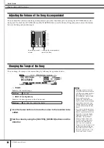
Page 29: ...or the PHONES jack This is independent from the MASTER slider setting For details about all of the sliders as well as the PHONES and MASTER see page 31 If the display is not easily visible use the Con...

Page 30: ...bal pad e g RHH135 illustrated below along with the Hi Hat Controller HH65 etc via the ways as illustrated below Keep in mind that the example RHH135 illustrated below is divided into two sections Op...

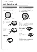
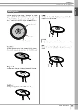
Page 31: ...ting the main surface of the pad bow section located between the cup and edge produces the Bow Shot sound Edge Shot Hitting the outside edge produces the Edge Shot sound Bell Shot Hitting the cup prod...

Page 32: ...off the BYPASS indication is shown with white text in black the Reverb Effect is applied to the Drum Kit sound When Bypass is turned on the BYPASS indication is shown with black text in white the Reve...

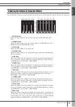
Page 33: ...nge the destination instruments or voices of which the volume is adjusted by setting the SliderSel parameter called up via DRUM KIT F2 VOICE SF4 OTHER G TOM slider Adjusts the volume of the toms You c...

Page 34: ...on to start the click sound The red lamp lights on the first beat of every measure when the click or a Song is playing The other beats are indicated with a green light Press the CLICK ON OFF button ag...

Page 35: ...You can select one of the following values B TEMPO Indicates the tempo value of the Click You can set the value over the following range 3 Move the cursor to theTEMPO or BEAT Time Signature by using...

Page 36: ...d indicated as a TEMPO value in the LCD display The Tempo value in the LED display will be replaced with the Drum Kit number in a few seconds after performing the Tap with the initial default status w...

Page 37: ...yourself Song Playback Select one of the DTX900 s Preset Songs and listen to it The Preset Songs include accompaniment with keyboard brass and other voices as well as drum sounds For a list of the Pr...

Page 38: ...performed 3 After moving the cursor to the Song number select the desired Song by using the INC YES button DEC NO button or data dial Changing the Song calls up the Drum Kit specified by the new Song...

Page 39: ...to the SF6 button In this condition you can use the SF1 SF5 and F1 F5 buttons as number but tons by pressing the SF6 NUM button For details see page 14 Repeat Playback NOTE The Song Repeat setting on...

Page 40: ...and the data dial Adjusting the overall volume Adjusting the accompaniment part of the Song 1 2 NOTE The tempo value can be shown on the LED display by setting the LED Display parameter in the dis pl...

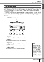
Page 41: ...DRUM Pressing this button toggles DRUM part playback on and off Mute This button does not affect the same part included in Track 2 of the Song B SF2 BASS Pressing this button toggles BASS part playbac...

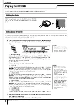
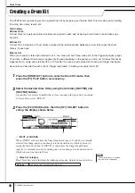
Page 42: ...ce Set for each of pads Trigger Input jacks to create your original Drum Kit 1 Press the DRUM KIT button to enter the Drum Kit mode then press the F1 PLAY button as necessary 2 Select the desired Drum...

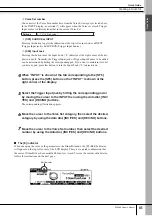
Page 43: ...he Input Lock L indicator on 4 When INPUT is shown at the tab corresponding to the SF5 button press the SF5 button so that INPUT is shown at the right corner of the display 5 Select the Trigger Input...

Page 44: ...RE button again The display prompts you for confirmation To cancel the Store operation press the DEC NO button 4 Press the INC YES button to execute the Store operation Storing the Edited Drum Kit Whe...

Page 45: ...d the performance data as it is played allowing you to capture all the nuances of an actual drum performance When replace is selected as Recording Type in the REC STANDBY display called up via the REC...

Page 46: ...track to be recorded C Quantize Determines the Record Quantize value Record Quantize automatically aligns the timing of notes as you record When the cursor is located at the Quantize value the note ty...

Page 47: ...to hear the newly recorded Song You can stop recording at the middle of the Song by pressing the button 11 Save the recorded Song to a USB storage device Settings 1 4 16 4 1 8 16 8 1 16 16 16 Range 0...

Page 48: ...revious data Recording Along With the Preset Song Although your drum performance cannot be recorded to a Preset Song you can add your own drum performance data to a Preset Song by copying the Preset S...

Page 49: ...this parameter to 2 Because the Preset Song data is recorded only to track 1 you can record your drum performance to track 2 along while track 1 plays back 9 Press the SF1 DRUM button to mute the drum...

Page 50: ...ar Track then press the ENTER STORE button to call up the Clear Track Job display 1 Track Indicates the track to be cleared 3 Select a track to be cleared If you have copied the Preset Song data to th...

Page 51: ...he ENTER STORE button to call up the Job display 1 Name Determines the Song name which can contain up to 10 characters For detailed instructions on naming refer to Basic Operation on page 15 B SF6 LIS...

Page 52: ...elected in the Note parameter This parameter lets you specify the third note timing of the triplet as correct In other words this determines how your swing feel will be evaluated with Groove Check NOT...

Page 53: ...which pads signals received via the Trigger Input jacks will be monitored by Groove Check Any or all pads can be selected and up to five differ ent pads can be monitored at once The ALL indication sh...

Page 54: ...pads can be selected and up to five different pads can be monitored at once The ALL indication shows the result for all sounds from all pads The NO ASGN indication means no pad is selected Lines show...

Page 55: ...sult for each hit accuracy of the hit timing is shown in the display in real time 7 Stop playback then confirm the result of the Rhythm Gate For details on the Rhythm Gate display indications see belo...

Page 56: ...ment File Folder Selection The illustrations and instructions below show you how to select files and folders on the USB storage devices within the File mode NOTE For details about USB storage devices...

Page 57: ...t character list for easier name entry by pressing the SF6 button 5 Press the Cursor M M M M button to move the cursor to the file direc tory select box then select a destination directory This step i...

Page 58: ...to be loaded If the file is saved under any directory select the directory including the desired file then press the ENTER STORE button to find the desired file 5 Press the SF1 EXEC to execute the Loa...

Page 59: ...one Generator Drum Kit Created by assigning a Drum Voice to each of the Trigger Input Sources on the pad The following banks are available Preset Drum Kit User Drum Kit External Drum Kit A P Drum Voic...

Page 60: ...zone pads generating multiple types of trigger signal The PCY65S generates two different types of trigger signals and the PCY155 generates three different types of trigger signals depending on where...

Page 61: ...of trigger signals generated by using a 3 zone pad and turning the Snappy setting On Off Hi Hat Controllers generating different types of trigger signals according to the pressure applied Hi Hat cymb...

Page 62: ...tions of trigger signals are recognized Indicates the corresponding pad model is compatible with 2 zone pads In case of the RHH model two types bow and edge sections of trigger signals are recognized...

Page 63: ...ection of the tom pad e g XP120T tom4Rm2 Tom 4 Rim 2 5 TOM4 Hitting the rim 2 section of the tom pad e g XP120T rideBw Ride Cymbal Bow 6 RIDE Hitting the bow section of the cymbal pad rideEg Ride Cymb...

Page 64: ...reating your own original Drum Kits Drum Voices assigned to each of the Trigger Input Sources You can create your own original Drum Kit by assigning the desired Drum Voice to each of the Trigger Input...

Page 65: ...sound by making Voice Set assignments for each of the Trigger Input jacks and create your original Drum Kit If you want to go even further you change the sound and create a Drum Kit by assigning Drum...

Page 66: ...buttons in order setting the SOURCE to MIDI then selecting a MIDI note number on the NOTE NO column From this display you can change the Drum Voice assigned to the MIDI note number meaning that you c...

Page 67: ...e temporarily in the optionally installed DIMMs pages 76 and 147 Because data contained in DIMM is lost when the power is turned off you should always save the User Voices created by recording editing...

Page 68: ...signal exceeds the Trigger Level SAMPLING F6 REC Trigger Mode level After pressing the F6 START button in the Sampling Standby display sampling starts as soon as a strong enough audio signal is receiv...

Page 69: ...this data is transmitted to the tone generator block for the sounds to be played back Playback of each Song can be started by hitting the specified pad as well as pressing the Start Stop button The f...

Page 70: ...EFFECT SF1 CONNECT or SF4 CHORUS The Effect of this block is applied to the overall sound of the DTX900 Variation The Effects of this block is applied only to the current Drum Kit sound The Effect ty...

Page 71: ...Audio signal via AUX IN SAMPLING IN Drum Voice MIDI channel 10 Other Voices Other than MIDI channel 10 Master Effect Master EQ Click Voice Variation 1 Variation Return 1 Variation Send 2 Chorus 1 Rev...

Page 72: ...mation to the sound DISTORTION This effect type is used mainly for guitar adding distortion with an edge to the sound WAH This effect cyclically modulates the tone brightness cutoff frequency of a fil...

Page 73: ...ology R3 ROOM Reverb emulating the acoustics of a room using an algorithm derived from the Yamaha ProR3 SPX ROOM Reverb emulating the acoustics of a room derived from the Yamaha SPX1000 R3 PLATE Rever...

Page 74: ...eters below may appear in different effect types with the same name but actually have different functions depending on the partic ular effect type For these parameters two or three types of explanatio...

Page 75: ...of the low pass filter applied to the dry sound DryLvl Determines the level of the dry sound the unproc essed sound DryMixLvl Determines the level of the dry sound the unproc essed sound DrySndNoise...

Page 76: ...the wave sine or square For AUTO PAN Determines the panning curve Paramater name Descriptions Livenss Determines the decay characteristics of Early Reflec tion LowAtk Determines the amount of time fro...

Page 77: ...elease Determines the amount of time that elapses between the release or end of a sound and the end of the compressor effect RelTime Determines the release time of the envelope follower Reso Determine...

Page 78: ...er is turned off Because of this you should always store any data residing in DRAM to the USB stor age device before turning off the power DIMM sold separately DIMM modules must be installed in order...

Page 79: ...e loaded in the File mode with the File type Song as a User Song Memory Structure Drum Kit Voice Song Trigger Setup Preset data ROM Internal Memory User Memory Flash ROM DRAM DIMM Data Creation functi...

Page 80: ...SOURCE is selected you can edit the parameters for each Trigger Source page 61 2 2 Select the Trigger Input jack or Trigger Input Source by hitting the corresponding pad or by using the INC YES DEC N...

Page 81: ...at 2 D SF5 SOURCE Pressing the SF5 button toggles the display type between INPUT meaning that parameters can be edited for each Trigger Input jack and SOURCE meaning that parameters can be edited for...

Page 82: ...age when the SOURCE display is called up and MIDI is selected 1 Volume When the INPUT display is called up this parameter for which the value is indicated in the knob icon determines the volume of eac...

Page 83: ...display is called up this parameter for which the value is indicated in the knob icon determines the unprocessed dry level of the Reverb Chorus effects signal for each selected Trigger Input Jack When...

Page 84: ...INPUT display is called up this parameter for which the value is indicated in the knob icon determines the amount of boost or attenuation applied to the middle EQ band for each selected Trigger Input...

Page 85: ...ob icon determines the release time of each selected Trigger Input Jack When the SOURCE display is called up this parameter determines the release time of each selected Trigger Input Source L Filter W...

Page 86: ...er Input Jack responds to MIDI Note Off messages When the SOURCE display is called up this parameter determines whether or not each selected Trigger Input Source responds to MIDI Note Off messages Thi...

Page 87: ...ter determines how the played velocities of each selected Trigger Input Source affect the actual result ing velocity This lets you raise or lower all velocities by the same amount allowing you to auto...

Page 88: ...as that at the current cursor location without affecting the num bers of the other steps E SF3 DELETE Pressing this button deletes the step at the current cursor loca tion If the step number is gone b...

Page 89: ...ge The second page 1 VELOCITY LIMIT Determines the minimum and maximum values of the veloc ity range within which the Drum Voice will sound The Drum Voice will sound only when you hit the pad at veloc...

Page 90: ...he MIDI keyboard make the appropri ate settings so that the MIDI connector is active If the MIDI keyboard is equipped with a USB TO HOST ter minal you may need to manually enable MIDI operation depend...

Page 91: ...ition of the Variation effect sound J Chorus Return Determines the Return level of the Chorus Effect K Chorus To Reverb Determines the Send level of the signal sent from the Chorus Effect to the Rever...

Page 92: ...the Drum Kit sound 1 Type Equivalent to 5 of the SF1 CONNECT display You can select the Reverb Effect type from the Type column B Preset You can set various parameters in order to change how the sound...

Page 93: ...ing on the currently selected effect type Refer to page 72 for details about the Effect parameters Refer to the sepa rate Data List booklet for information on the parameters for each Effect type E PAG...

Page 94: ...counter clockwise makes the Drum Voice sound more muffled or darker Turning the Pad Controller to the right clockwise makes the Drum Voice sound brighter voice Turning the Pad Controller sets the snap...

Page 95: ...s to your pad hit ting When play is selected hitting the pad starts or stops the specified Song When chase is selected hitting the pad plays only one measure of the specified Song When cutoff is selec...

Page 96: ...put Source from the same group respectively generate a MIDI note off event for the corresponding MIDI note number The RcvKeyOff parameter for the drum Voice 10 ch should be set to on in the display ca...

Page 97: ...er connected to the HI HAT jack page 12 1 Function Determines the function assigned to the Hi Hat Controller When Hi Hat is selected you can use the Hi Hat Controller normally for playing the hi hat c...

Page 98: ...e set to on When all is selected both Program Change and Control Change messages will be transmitted When PC is selected only Program Change messages will be transmitted D VOLUME Determines the value...

Page 99: ...ck Voice Set Trigger Input Source Voice or MIDI MIDI note B Source Drum Kit number Determines the Drum Kit number used as the source Cur rent means the currently edited Drum Kit C Copy Source Determin...

Page 100: ...r off Make sure to save the Song data in the File mode to an external USB storage device con nected to the USB TO DEVICE terminal before turning the power off Functions Descriptions SF1 SONG Song Job...

Page 101: ...urrent Song 1 Song number Determines the source Song number to be copied The corre sponding Song name is shown at right of the Song number 02 Clear Song This Job clears all data from the current Song...

Page 102: ...d value by pressing the SF6 button to call up the value list 16th note triplet 16th note 8th note triplet 8th note 1 4 note triplet 1 4 note Dotted 1 4 note C SF6 note type icon When the cursor is loc...

Page 103: ...ed at 1 C Starting measure number of source measure range Determines the starting measure of the source measure range D Ending measure number of source measure range Determines the ending measure of t...

Page 104: ...d meter data following the deleted measures are moved forward accordingly 1 Track Determines the track number to be deleted When 1 2 is selected executing the Job removes the specified measures from b...

Page 105: ...nel You can specify a specific Voice by set ting the Bank Select MSB LSB and Program Change Voice number G F4 PRE KIT This menu appears only when the cursor is located on any of the VCE NUM BANK MSB a...

Page 106: ...e the tab menus corresponding to the F1 F5 and SF1 SF3 buttons to find the desired function then press the relevant button to call up the desired dis play 3 Move the cursor to each parameter then set...

Page 107: ...timing for quarter notes G VOLUME eighth notes Determines the volume of click timing for eighth notes H VOLUME sixteenth notes Determines the volume of click timing for sixteenth notes I VOLUME eighth...

Page 108: ...e 51 Explanations about this display are described in the Quick Guide section on page 52 Explanations about this display are described in the Quick Guide section on page 50 Settings kick1 2 snare1 3 t...

Page 109: ...ures repeatedly This function can be effectively used to bring your rhythm technique and timing up to a higher level letting you play a certain drum phrase for several measures while listening to the...

Page 110: ...STORE button The following display will appear 5 Select the destination Trigger Setup num ber by using the data dial 6 Press the ENTER STORE button The following display prompts you for confirmation b...

Page 111: ...is converted to the velocity recognized by the tone generator block Keep in mind that the level and velocity generated by hitting a pad are shown at the top of the LCD display in real time 1 INPUT Tri...

Page 112: ...nerated via double triggering C Reject Level From ALL Determines the minimum level of the trigger signals gener ated by hitting any other pads which the current Trigger Input jack will accept In other...

Page 113: ...ce C Trigger Setup number as copy destination Determines the Trigger Setup number as copy destination Current refers to the currently edited Trigger Setup D Trigger Input jack as copy destination Dete...

Page 114: ...ding the User Voices consisting of audio signals obtained via the Sampling function is much larger than other files File sizes are indicated in conventional computer terms by B Byte KB Kilo Byte MB Me...

Page 115: ...e as an AIFF file Mac intosh audio format File types File extension Information AllData T3A Files of the AllData type saved to the USB storage device can be loaded and restored to the instrument Utili...

Page 116: ...from the File Directory Folder selection box to the File name input location G F6 NEW Pressing this button creates a new directory named NEWDIR within the currently selected directory You can change t...

Page 117: ...t location then input a file name For detailed instructions on naming refer to Basic Opera tion on page 15 You can call up the Character List by pressing the SF6 but ton 4 Select the destination direc...

Page 118: ...box on the display 3 Move the cursor to the Directory File list box then select the file to be loaded You can select any of the files listed in the Directory File list box on the display 4 Press the...

Page 119: ...number for the Load destination 7 Press the SF1 EXEC button again to exe cute the Load operation You can also load a single specific Song from the file File extension T3A or T3S to the desired User So...

Page 120: ...he Load destination 7 Press the SF1 EXEC button again to exe cute the Load operation You can also load a single specific Chain from the file File extension T3A or T3H to the desired Chain number 1 Pre...

Page 121: ...nk and number for the Load destination 7 Press the SF1 EXEC button again to exe cute the Load operation Any audio data created and edited on a computer and saved in the WAV or AIFF format can also be...

Page 122: ...plied to the settings on the Voice Job display called up via SONG F2 JOB SF4 VOICE The settings on the Voice Job are not transmitted to the internal tone generator or the external MIDI device even whe...

Page 123: ...folder while pressing the EXIT button returns to the next highest directory You can distinguish the directory and file by the indicator at left end of each line Directory Folder File C File name inpu...

Page 124: ...o be deleted belongs For details about the File type see page 113 3 Move the cursor to the Directory File list box then select the file to be deleted 4 Press the SF1 EXEC button A confirmation message...

Page 125: ...o Basic Operation on page 15 B SF1 EXEC Pressing this button executes the Format operation C SF6 LIST You can call up the Character List by pressing this button Refer to Using the character list page...

Page 126: ...cted 1 Volume Determines the overall volume for the tone generator The lower the value the lower the actual volume will be when set ting the slider on the front panel to maximum B Pan Depth Determines...

Page 127: ...and other files will not be loaded B LED Display Determines the information which is indicated on the LED dis play When KitNo is selected the current Drum Kit number is indicated on the LED display W...

Page 128: ...o which the specified function is assigned When Input Lock page 79 is turned off you can select the Trigger Input Source also by hitting the corresponding section of the pad B PadFunc Determines the f...

Page 129: ...tenuated boosted by the Gain setting LOW When the Shape is set to shelv 32Hz 2 0kHz When the Shape is set to peak 63Hz 2 0kHz LOWMID MID HIGHMID 100Hz 10kHz HIGH 500Hz 16kHz C GAIN Determines the leve...

Page 130: ...he AUX IN SAMPLING IN jack B Pan Determines the stereo pan position of the audio signals input via the AUX IN SAMPLING IN jack C Mono Stereo Determines the signal configuration for the audio signals i...

Page 131: ...ect Types applied to the audio signals input via the AUX IN SAM PLING IN jack 1 Category B Type From the Category column you can select one of the Effect Categories each of which contains similar Effe...

Page 132: ...ve Program Change messages from the external MIDI device When set to off the DTX900 will ignore them C ReceivePC10ch Determines whether or not the DTX900 receives Program Change messages over MIDI cha...

Page 133: ...ber which can be set here to a separate tone generator con nected to the MIDI OUT terminal C Merge This parameter allows you to mix incoming MIDI data received via MIDI IN with MIDI data generated on...

Page 134: ...Drum Kit number and name D SONG Indicates the currently specified Song number and name E CLICK Indicates the currently specified tempo and time signature 3 Move the cursor to the Chain number then sel...

Page 135: ...umber called up when the corresponding Step is selected 3 Program the Chain Setting the parameters for each Step Move the cursor to Step 01 then set the desired TYPE by using the data dial INC YES and...

Page 136: ...d Selecting the next Step calls up the settings of Steps 02 04 simultaneously Naming the Created Chain F3 NAME From this display you can enter the desired name for the current Chain up to eight charac...

Page 137: ...o the AUX IN SAMPLING IN jack on the rear panel 3 Turn the power of the DTX900 on 4 Press the UTILITY button to enter the Utility mode press the F4 AUXIN button then press the SF1 OUTPUT button to cal...

Page 138: ...tting display then make the necessary settings From this display you can set the basic parameters such as recording source and sampling frequency 1 Source Sampling Source Determines the input connecto...

Page 139: ...ampling Recording operation you can set the appropriate gain by checking the volume via the Level Meter while hitting the pad E F6 START Press this button to start Sampling When the Trigger mode 1 is...

Page 140: ...igned Voice 12 If you are satisfied with the results press the F5 OK button to store the sampled sound as a User voice The F1 SELECT display appears again 13 If necessary repeat steps 5 12 to assign a...

Page 141: ...in the waveform display When the cursor is not located on the Loop parameter the Loop Point is indicated as a vertical dotted line in the waveform display C End End Point Determines the End point for...

Page 142: ...ide show ing the Start Point area and the right side showing the End Point area Pressing the F5 DISPLAY in this condition alter nates between the split screen display and a display showing either the...

Page 143: ...atches the settings of the Beat time signature and Measure B Beat Time signature Determines the time signature of User Voice playback Setting the value here changes the End Point so that the length be...

Page 144: ...as been modified temporarily and is not fixed as data 8 Press the F6 OK button if you are satis fied with the result of the Job operation If you are not satisfied with the result of the Job operation...

Page 145: ...ength of the User Voice also changes the playback tempo of the audio data included in the User Voice 1 Ratio Determines the length of the post process Voice as a ratio of the length of the original Vo...

Page 146: ...convert a stereo User Voice to a mono User Voice 1 Type Determines which channel or both channels of the stereo User Voice will be converted to a mono User Voice L R mono The left and right channels...

Page 147: ...after executing the Slice operation you can assign each of the slices to a different User Voice Set the Select parameter to the desired slice number set the Save To parameter to the User Voice num be...

Page 148: ...memory all unnecessary audio data included in the User Voice located ahead of the Start Point and located after the End Point leaving only the portion of the sample you wish to keep 1 User Voice bank...

Page 149: ...Then remove all cables connecting the instrument to other devices Leaving the power cord connected while working can result in electric shock Leaving other cables connected can interfere with work Be...

Page 150: ...ng a Phillips screwdriver 4 Insert the two DIMMs into the DIMM sock ets Location for DIMM installation Installing the DIMM modules to the sockets 4 1 Press the ejector levers to the outside of the soc...

Page 151: ...tton then press the SF6 INF button page 136 If the DIMMs have been installed properly the appro priate available memory size is indicated in the display 1 Press the ejector lever until the DIMM unlock...

Page 152: ...be produced depending on the settings of these parameters Check the Effect and Filter settings No sound may be produced especially depending on the Filter settings The external MIDI tone generator pro...

Page 153: ...the dis play called up via UTILITY F5 MIDI SF3 OTHER If you are connecting a computer to the DTX900 via USB this parameter should be set to USB if you are connecting a MIDI device to the DTX900 via MI...

Page 154: ...continue when the Receive Key Off parameter is set to off in the display called up via DRUM KIT F2 VOICE SF4 OTHER The Pad Controller does not work as expected Check the Pad Controller Type parameter...

Page 155: ...annot be loaded in the current mode Illegal file name The specified file name is invalid Try entering a different name Illegal input An invalid input or value has been specified Check the input method...

Page 156: ...not be exe cuted Seq data is not empty This message appears if you attempt to record to a track that already contains data Clear the track data in the Song Job mode or select a different track then pe...

Page 157: ...set 8 User 1 Training Functions Measure break Groove check Rhythm gate Sampling Samples 1 016 for the User Voices Sampling Sources Audio input signals via AUX IN SAMPLING IN Audio output signals via O...

Page 158: ...146 Delete All 146 Delete Measure 102 Demo Songs 35 Destination Drum Kit number 97 Destination measure number 101 Destination Track number 101 DeviceNo 131 DIGITAL OUT connector 12 DIMM 76 147 DISPLA...

Page 159: ...114 121 Normalize 143 Note 50 NOTE NO 87 Note number 80 NUM 140 NUMBER Chain number 132 Number of measures to be inserted 102 O Open Rim Shot 28 Open Close 28 Optimize Memory 146 OTHER 39 OUTPUT L MO...

Page 160: ...ger Input jack as copy source 111 Trigger Input Level Indicator 22 Trigger Input Source 58 61 Trigger Level 137 Trigger No 125 Trigger Setup 22 60 Trigger Setup List 23 Trigger Setup number 22 Trigger...

Page 161: ...everse engineering disassembly decompilation or other wise deriving a source code form of the SOFTWARE by any method whatsoever You may not reproduce modify change rent lease or distribute the SOFTWAR...

Page 162: ......

Page 163: ...MEMO...

Page 164: ...208POTO A0 C S G Digital Musical Instruments Division 2012 Yamaha Corporation Printed in Japan ZD45090 Yamaha web site http www yamaha com Yamaha Downloads http download yamaha com...

Reviews: