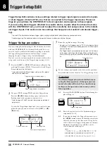
8 Trigger Setup Edit
38
DTXPRESS
IV
Owner’s Manual
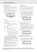
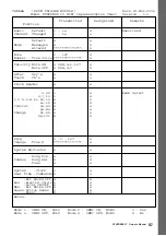
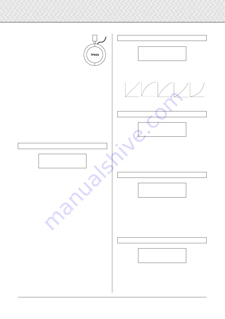
*1 Three-zone function (pad voice x 1, rim
voice x 2) is available if a three-zone
compatible pad such as the TP65S, etc.
is connected to the
1
SNARE,
5
RIDE,
or
6
CRASH input.
For producing closed rim shots, the
“
TP2/SnrA
” has a high sensitivity set-
ting on rim 1, while the “
TP2/SnrB
” has
a high sensitivity setting on rim 2.
The same voice is assigned to “
TP2/
Tom
” and “
TP2/SnrA
” and the left and
right rim sensitivities are set to the same level.
*2 Rim1 and rim2 sounds on the “
TP2/SnrB
” are reversed from
those on “
TP2/SnrA
”. This provides left-handed drummers
with a proper setting when using a left-handed setting.
*3 When a stereo pad such as the TP80S is connected to the
1
SNARE,
5
RIDE, or
6
CRASH input, “
TP3-A
” will produce
the sound that is assigned to rim 1, and “
TP3-B
” will produce
the sound assigned to rim 2 (p. 28)
*4 When using an RHP series stereo pad, connect the pad to
Input
2
TOM1/10,
3
TOM2/11,
4
TOM3/12, or
8
KICK/9,
and set the pad type in “
™tom1
”, “
£tom2
”, “
Ωtom3
”, or
“
äkick
” input to “
RHP
~
pad
” and the pad type in “
ƒπpad10
”,
“
ƒƒpad11
”, “
Īpad12
”, or “
“pad9
” to “
RHP
~
rim
.”
*5 To use the BP80 as a stereo pad, connect the pad to Input
2
TOM1/10,
3
TOM2/11,
4
TOM3/12, or
8
KICK/9.
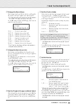
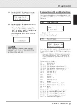
Gain
[Range]
0–99
Adjusts the input gain (sensitivity) for the input jack assigned in
the upper half of the page.
Setting a larger value lets a smaller input level from the pad cre-
ate sound.
* This value will be automatically set after the appropriate pad
type is set in [TRG2 Type (Pad Type)]. Some fine-tuning of the
value will be necessary.
* Some pads are equipped with a sensitivity adjustment knob.
For details, refer to the owner’s manual that came with the
particular pad.
MVI
[Range]
1–127
Sets the MIDI Velocity (volume) that is transmitted when the pad
is hit the softest. Large values will produce a high volume level
even if the pad is hit softly. However, this will result in a narrow
volume range making it difficult to adequately produce wider
dynamic levels.
The Trigger Input Level will be displayed in percentage in the
upper right hand corner of the display. The maximum velocity
(input level 99 percent) will be 127. The lower the level is when
the pad is hit the weakest, the wider the potential dynamic range
will be.
* This value is automatically set after the appropriate pad type
is set in [TRG2 Type (Pad Type)]. Some fine-tuning of the
value will be necessary.
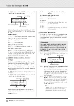
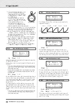
Sets the Input Velocity Curve for the input jack assigned in the
upper half of the page.
[Range]
0–9
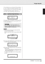
Prevents double triggering from occurring in the input jack
assigned in the upper half of the page. After an event is detected,
further events will be automatically muted for a certain length of
time. The larger the value, the longer time events will be muted.
[Range]
0–9
Prevents crosstalk from occurring in the input jack assigned in
the upper half of the page. Events triggered by other pads (input
jacks) that are of a lower input value than what is set here will not
be triggered for a certain length of time. Larger values require a
greater input level in order to produce a trigger event.
RejLvl [Range]
0–9
Frm
[Range]
1–6, 56 (5 and 6), 7–12
This setting is used to prevent crosstalk between the input jack
assigned in the upper half of the page and the input jack assigned
in the “
Frm=
” setting.
TRG3
Gain, MVI (Minimum Velocity)
Rim 1
Rim 2
TRG3
~
ƒsnare
~~
0%
”Gain=65MVl=
~
12‚
TRG4
VelCurve (Velocity Curve)
TRG5
RejTime (Self Rejection Time)
TRG6
RejLvlAll (Rejection Level)
TRG7
RejLvl (Specified Rejection Level)
TRG4
~
ƒsnare
~~
0%
”VelCurve=norm
~
‚
norm
loud2
loud1
hard1
hard2
V
elocity
→
Strength of hit
→
TRG5
~
ƒsnare
~~
0%
”
~~
RejTime=1
~~~
‚
TRG6
~
ƒsnare
~~
0%
”
~
RejLvlAll=2
~~
‚
TRG7
~
ƒsnare
~~
0%
”RejLv1=3Frm=56‚

