13
DTXTREME
Ⅲ
5.
DM Circuit Board
(Time required: About 9 minutes)
5-1
Remove the side cover L and R. (See procedure 1.)
5-2
Remove the bottom case. (See procedure 2.)
5-3
Remove the JK circuit board. (See procedure 3.)
5-4
Remove the DMSUB circuit board.
5-5
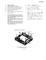
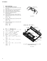
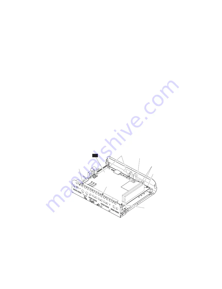
Remove the following screws and remove the DM
circuit board. (Fig. 5)
[410D]:
6pcs.
*
The optional DIMM is not part of the DM circuit
board. When replacing the DM circuit board, re-
move the optional DIMM, and install it to a new
DM circuit board. (Fig. 5)
*
When replacing the DM circuit board, save the
whole internal setup data on a USB memory.
(See page 83)
*
When the connector assembly is disconnected
from the connector CN18, the protection sheet
will be disconnected as well. Take care not to
lose the protection sheet.
5.
DM シート
(所要時間:約 9 分)
5-1
サイドカバー L、R を外します。
5-2
5-3
JK シートを外します。
5-4
DMSUB シートを外します。
5-5
下記のネジを外して、
DM シートを外します。
(図 5)
[410D]:
6 本
※
拡張メモリー(オプション)は DM シートの構成
部品ではありません。DM シートを交換する際は、
拡張メモリーを取り外して、新しい DM シートに
取り付けてください。(図 5)
※
DM シートを交換する際は、内部の全ての設定デー
タを USB メモリーにセーブ(保存)してください。
※
コネクタ CN18 から線材を外した時、保護シート
も外れますので、紛失しないよう注意しててくだ
さい。
<Bottom view
(底から見た図)
>
[410D]
[410D]
DM
[410D]
[410D]
[410D]
Optional DIMM
(拡張メモリー)
Protection sheet
(保護シート)
[410D]: Bind Head Tapping Screw-B(B タイト+ BIND)
3.0X8 MFZN2W3 (WE774300)
Fig. 5 ( 図 5)
Summary of Contents for DTXTREME III
Page 30: ...DTXTREMEⅢ 30 B B DM Circuit Board 2NA WJ91030 2 ...
Page 31: ...31 DTXTREMEⅢ B B Pattern side パターン側 2NA WJ91030 2 ...
Page 34: ...DTXTREMEⅢ 34 D D DMSUB Circuit Board 2NA WJ91040 ...
Page 35: ...35 DTXTREMEⅢ D D Pattern side パターン側 Scale 85 100 2NA WJ91040 ...
Page 38: ...DTXTREMEⅢ 38 F F JK Circuit Board 2NA WJ91050 2 ...
Page 39: ...39 DTXTREMEⅢ F F Pattern side パターン側 Scale 95 100 2NA WJ91050 2 ...
Page 42: ...DTXTREMEⅢ 42 H H or D PN Circuit Board 2NA WJ91060 2 ...
Page 43: ...43 DTXTREMEⅢ H H Pattern side パターン側 Scale 80 100 2NA WJ91060 2 ...


