15
DTXTREME
Ⅲ
7.
Display Assembly
(Time required: About 11 minutes)
7-1
Remove the side cover L and R. (See procedure 1.)
7-2
Remove the bottom case. (See procedure 2.)
7-3
Remove the JK circuit board. (See procedure 3.)
7-4
Remove the DMSUB circuit board.
7-5
Remove the DM circuit board. (See procedure 5.)
7-6
Remove the PN circuit board. (See procedure 6.)
7-7
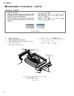
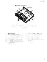
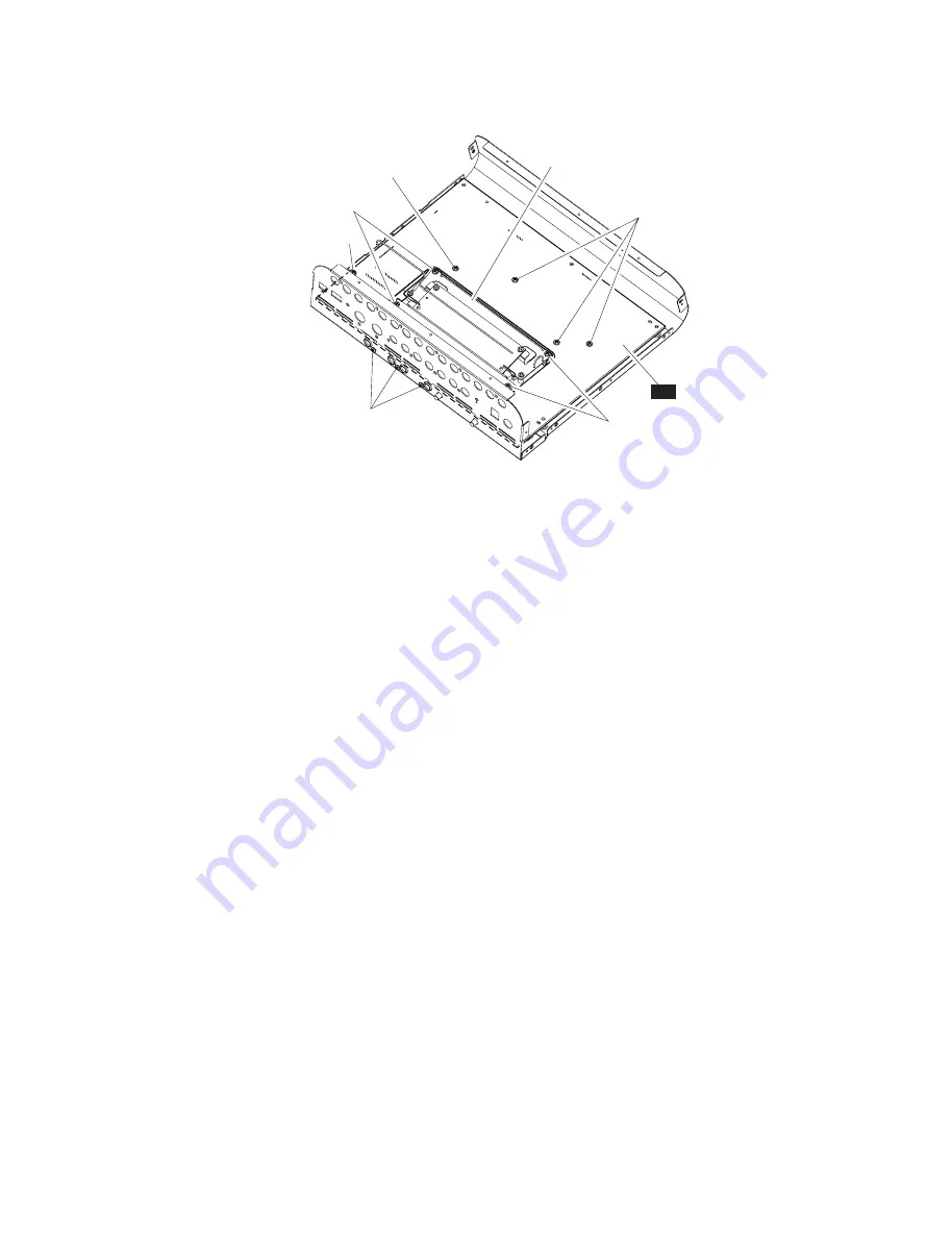
Remove the following screws and remove the dis-
play assembly. (Fig. 8)
[410H]:
4pcs.
7.
ディスプレイ Ass'y
(所要時間:約 11 分)
7-1
サイドカバー L、R を外します。
7-2
ボトムケースを外します。
7-3
JK シートを外します。
7-4
DMSUB シートを外します。
7-5
DM シートを外します。
7-6
PN シートを外します。
7-7
下記のネジを外して、ディスプレイ Ass y を外し
ます。
(図 8)
[410H]:
4 本
[390C]:
Bind Head Tapping Screw-B(B タイト+ BIND)3.0X10 MFZN2B3 (WE972200)
[410G], [410H]: Bind Head Tapping Screw-B(B タイト+ BIND)3.0X8 MFZN2W3 (WE774300)
Fig. 8 ( 図 8)
<Bottom view
(底から見た図)
>
[410H]
[410H]
PN
[410G]
[390C]
[410G]
Display assembly
(ディスプレイAss
’
y)
[410G]
Summary of Contents for DTXTREME III
Page 30: ...DTXTREMEⅢ 30 B B DM Circuit Board 2NA WJ91030 2 ...
Page 31: ...31 DTXTREMEⅢ B B Pattern side パターン側 2NA WJ91030 2 ...
Page 34: ...DTXTREMEⅢ 34 D D DMSUB Circuit Board 2NA WJ91040 ...
Page 35: ...35 DTXTREMEⅢ D D Pattern side パターン側 Scale 85 100 2NA WJ91040 ...
Page 38: ...DTXTREMEⅢ 38 F F JK Circuit Board 2NA WJ91050 2 ...
Page 39: ...39 DTXTREMEⅢ F F Pattern side パターン側 Scale 95 100 2NA WJ91050 2 ...
Page 42: ...DTXTREMEⅢ 42 H H or D PN Circuit Board 2NA WJ91060 2 ...
Page 43: ...43 DTXTREMEⅢ H H Pattern side パターン側 Scale 80 100 2NA WJ91060 2 ...


